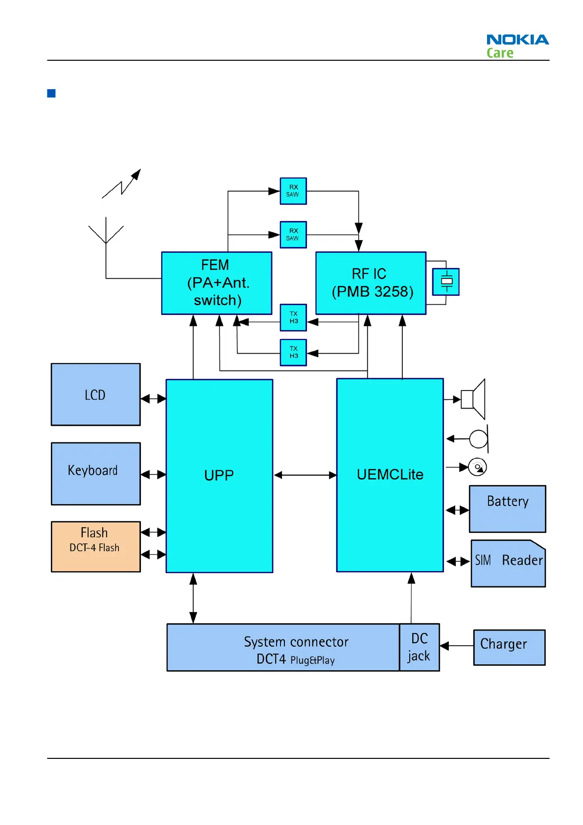
System module block diagram
The main board consists of a radio frequency part and a baseband part. The User Interface parts are situated
at the UI side, which is on the opposite side of the engine board. The 2CP is the engine module of the mobile
device, and the 2CQ is the UI module of module of the mobile device.
Figure 106 Module block diagram
RM-340; RM-341
System Module
Issue 1 COMPANY CONFIDENTIAL Page 6 –5
Copyright © 2007 Nokia. All rights reserved.
 Loading...