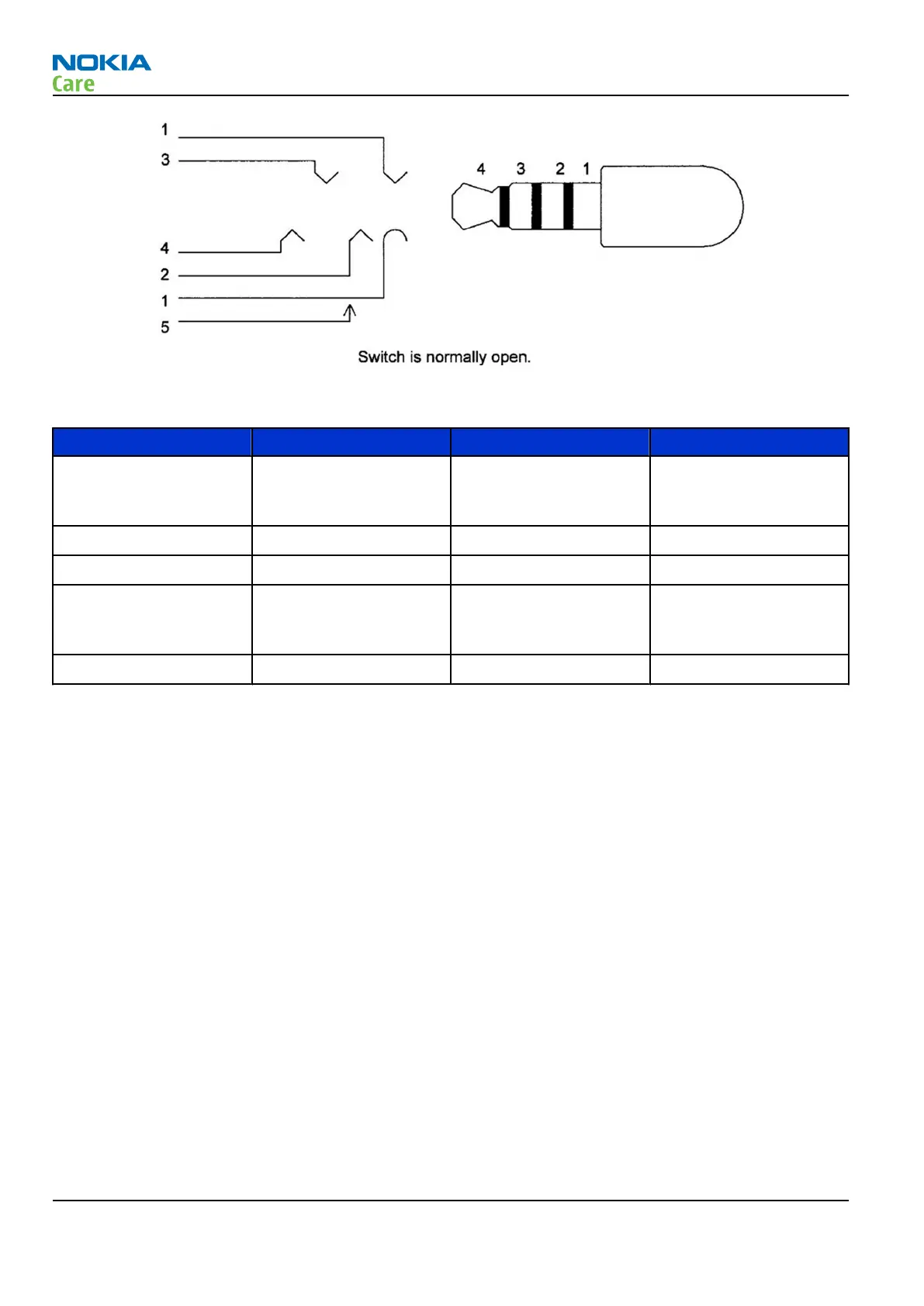
Figure 110 4-pole jack plug for audio accessory
Table 7 Connector for External Audio Accessories
Pin Signal name Direction Description
5 PLUGDET Input Terminal internal
connection, plug
detection
4 HS EAR L Output Audio output
3 HS EAR R Output Audio output
2 HS MIC Input Multiplexed
microphone audio and
control data
1 HS GND - Ground contact
HALL sensor
The HALL sensor is used to recognize the position of the flap.
The HALL sensor incorporates advanced chopper-stabilization techniques to provide accurate and stable
magnetic switch points. The circuit design provides an internally controlled clocking mechanism to cycle
power to the HALL element and analog signal processing circuits. This serves to place the high current-
consuming portions of the circuit into the sleep mode. Periodically the device is awakened by this internal
logic and the magnetic flux from the HALL element is evaluated against the predefined thresholds. If the flux
density is above or below the BOP/BRP thresholds, the output transistor is driven to change states accordingly.
While in the sleep cycle, the output transistor is latched in its previous state.
The output transistor of the SH248CSP is latched on at the presence of a sufficiently strong south or north
magnetic field facing the marked side of the package. The output is latched off in the absence of a magnetic
field.
The output of hall sensor is sent to GENIO24 of UPP. Baseband knows the status of the hall sensor that
represents the phone position (folded or not).
RM-340; RM-341
System Module
Page 6 –10 COMPANY CONFIDENTIAL Issue 1
Copyright © 2007 Nokia. All rights reserved.
 Loading...