DAA2 & DAX — P/N 53265:A1 8/24/2011 69
Installation BDA Backup Digital Amplifiers
The switches described in Table 4.3 are for configuring the BDA-25/70.
Table 4.3 BDA-25V/70V Switches
4.4 Installation
4.4.1 DAA2
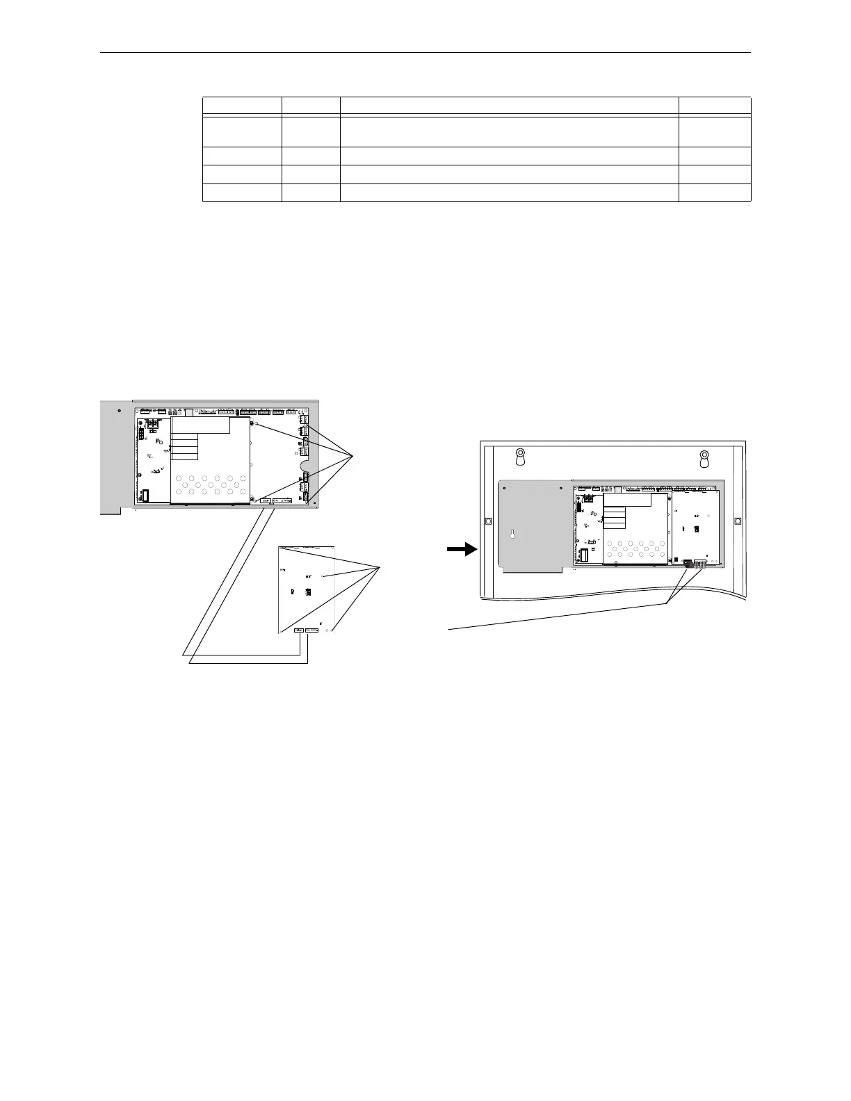
Figure 4.2 shows the installation of a BDA-25/70V onto a DAA2 amplifier. The BDA may be
programmed and wired for backup or for providing a second audio channel.
Figure 4.2 BDA-25V/70V Installation, DAA2
Name Switch # Description Default
FAIL TEST
SWITCH
SW4 Simulates an amplifier failure for testing backup amplfiers. Refer to
page 71.
Normal
75W SW5 Sets the board for 75 watt operation. Not populated for BDA-70’s. Disabled
50W SW6 Sets the board for 50 watt operation. Disabled
35W SW7 Sets the board for 35 watt operation. Disabled
1. Attach four
standoffs (p/n
42227) at
locations
indicated.
2. Align BDA
over standoffs.
Attach with four
screws.
3. Attach power
harnesses
(included with
BDA - refer to
Figure 4.4 on
page 70):
Power and
Control Harness
Connections
BDA
DAA2
• J1 on BDA to J6 on DAA2
• J2 on BDA to J5 on DAA2
J2
J1
J5
J6
 Loading...