page 6
FITTING MAIN LINE TO POWER UNIT
Your power unit is capable of being connected to the intake
vacuum trunk line from either side. Select the intake
connection to be used. Some installations may require the
connection into both intakes. The power unit has 4 intake
connections, which 2 of them are factory capped.
1. Using rubber coupling and hose clamp provided, attach the
utility valve assembly to the vacuum trunk line feeding into
the power unit. The utility valve can be installed on the left
or right hand side.
2. Cap off the unused intake tube with the plastic cap provided.
3. Attach exhaust tube to power unit using rubber coupling
and hose clamp provided (if vented to the outside).
4. Make sure all tubing connections are air tight.
5. The exhaust should NOT be vented into a wall, ceiling or
concealed space in the house. It is recommended to vent
the vacuum exhaust air to the outside of the house.
Exterior vented exhaust lines should be terminated using
Model V142 wall caps.
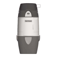
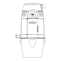
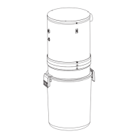
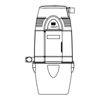
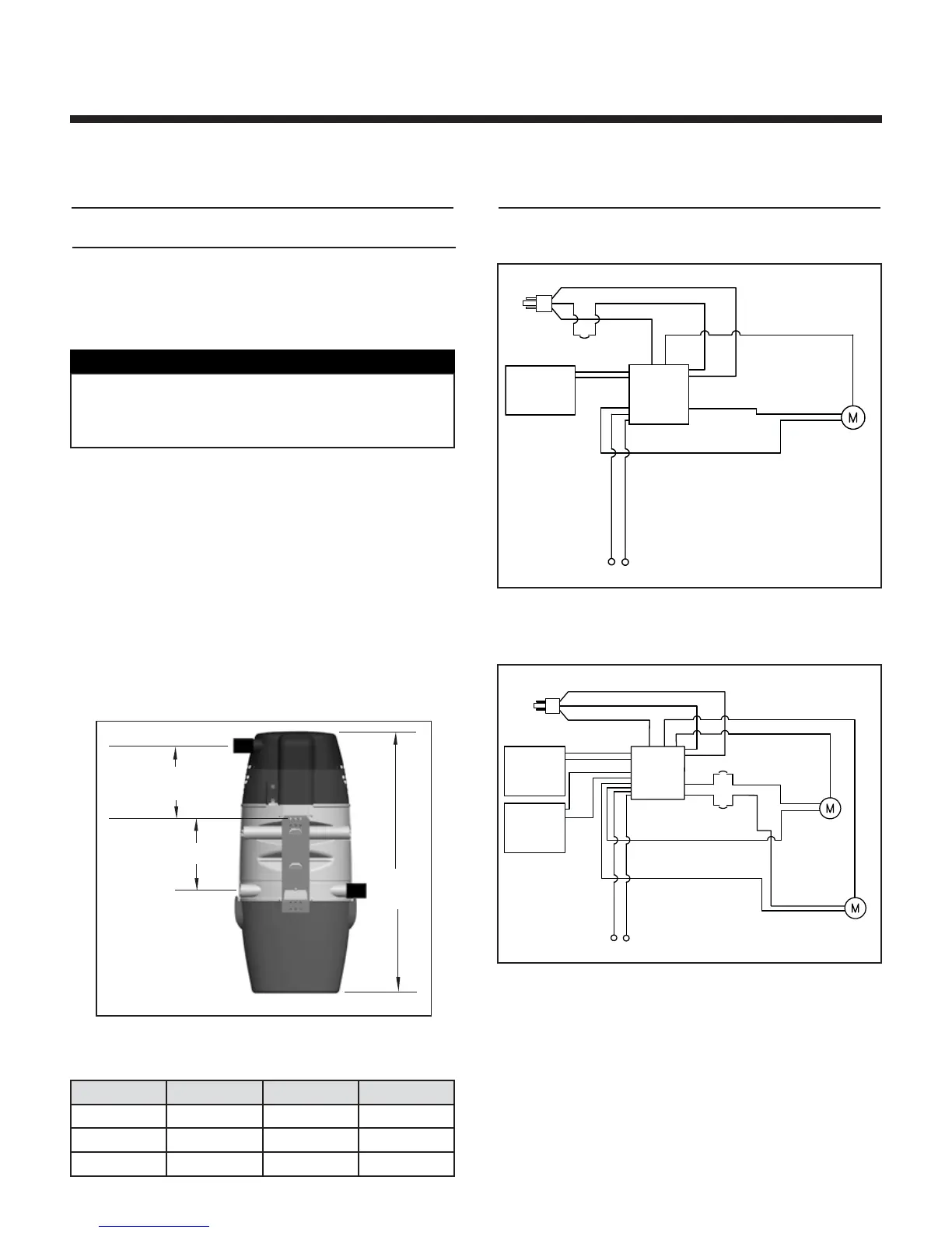
DIMENSIONAL CHART
Models VX475CC VX550CC VX1040CC
A 36
9
⁄16” 39
9
⁄16” 39
9
⁄16”
B 11” 11” 11”
C 10
7
⁄8” 10
7
⁄8” 10
7
⁄8”
CAUTION
NuTone VX475CC, VX550CC and VX1040CC power
units will attach to the lower intake connections.
See Fig. 10. Utility valve can be installed on either
side.
INTERNAL
WIRING DIAGRAMS
• VX475CC • VX550CC
 Loading...