Jetson Nano Developer Kit DA_09402_001_01 | 6
Interface Details
This section highlights some of the Jetson Nano Developer Kit interfaces. See the Jetson
Nano Developer Kit Carrier Board Specification for comprehensive information.
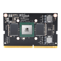
Module
• [J501] Slot for a microSD card.
• The passive heatsink supports 10W module power usage at 25° C ambient
temperature. If your user case requires additional cooling, you can configure the
module to control a system fan. See the Jetson Nano Supported Component List for fans
that have been verified for attachment to the heatsink.
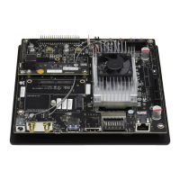
Carrier Board
• [DS3] Power LED; lights when the developer kit is powered on.
• [J2] SO-DIMM connector for Jetson Nano module.
• [J6] HDMI and DP connector stack.
• [J13] Camera connector; enables use of CSI cameras. Jetson Nano Developer Kit
works with IMX219 camera modules, including Leopard Imaging LI-IMX219-MIPI-
FF-NANO camera module and Raspberry Pi Camera Module V2.
• [J15] 4-pin fan control header. Pulse Width Modulation (PWM) output and
tachometer input are supported.
• [J18] M.2 Key E connector can be used for wireless networking cards; includes
interfaces for PCIe (x1), USB 2.0, UART, I2S, and I2C.
To reach J18 you must detach the Jetson Nano module.
• [J25] Power jack for 5V⎓4A power supply. Accepts a 2.1×5.5×9.5 mm plug with
positive polarity.
• [J28] Micro-USB 2.0 connector; can be used in either of two ways:
• If J48 pins are not connected, you can power the developer kit from a 5V⎓2A
Micro-USB power supply.
• If J48 pins are connected, operates in Device Mode.
• [J32 and J33] are each a stack of two USB 3.0 Type A connectors. Each stack is limited
to 1A total power delivery. All four are connected to the Jetson Nano module via a
USB 3.0 hub built into the carrier board.
• [J38] The Power over Ethernet (POE) header exposes any DC voltage present on J43
Ethernet jack per IEEE 802.3af.
• [J40] 8-pin button header; brings out several system power, reset, and force recovery
related signals (see the following diagram).

 Loading...