Jetson Nano Developer Kit DA_09402_001_01 | 7
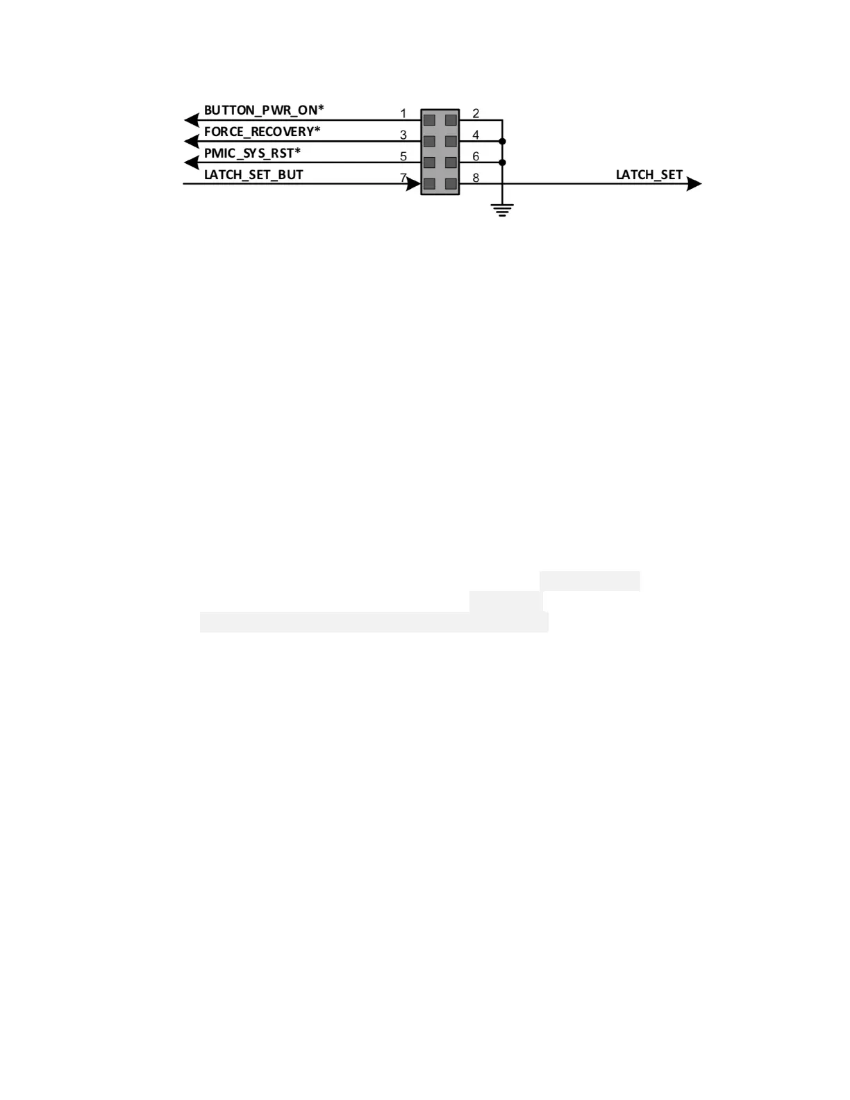
• Pins 7 and 8 disable auto power-on.
• Pins 1 and 2 initiate power-on if auto power-on is disabled.
• Pins 5 and 6 reset the system.
• Pins 3 and 4 put the developer kit into Force Recovery Mode if they are
connected when it is powered on.
• [J41] 40-pin expansion header includes:
• Power pins.
Two 3.3V power pins and two 5V power pins. These are not switchable; power is
always available when the developer kit is connected to power.
Two 5V pins can be used to power the developer kit at 3A each.
• Interface signal pins.
All signals use 3.3V levels.
By default, all interface signal pins are configured as GPIOs, except pins 3 and 5
and pins 27 and 28, which are I2C SDA and SCL, and pins 8 and 10, which are
UART TX and RX. L4T provides a Python library, Jetson.GPIO, for controlling
GPIOs. The library has the same API as RPi.GPIO. See
/opt/nvidia/jetson-gpio/doc/README.txt on your Jetson system for
details.
• [J43] RJ45 connector for gigabit Ethernet.
• [J44] 3.3V serial port header; provides access to the UART console.
• [J48] Enables either J28 Micro-USB connector or J25 power jack as power source for
the developer kit. Without a jumper, the developer kit can be powered by J28 Micro-
USB connector. With a jumper, no power is drawn from J28, and the developer kit
can be powered via J25 power jack.
Power Guide
Jetson Nano Developer Kit requires a 5V power supply capable of supplying 2A current.
Micro-USB Power Supply Options
Out of the box, the developer kit is configured to accept power via the Micro-USB
connector. Note that some Micro-USB power supplies are designed to output slightly
more than 5V to account for voltage loss across the cable. For example, Adafruit’s

 Loading...