5 ASSEMBLY
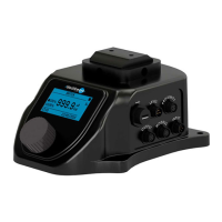
The KIT PRO /KIT PRO UL can be supplied in two versions:
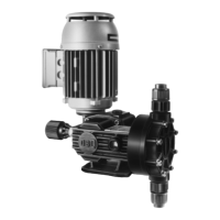
- Assembled on an OBL metering pump (Black Line series)
- The assembly kit can be assembled and installed on an OBL Black Line 2.0 metering pump
(manufactured from May 2017 onwards)
The KIT PRO must be assembled on pumps not installed in a system. Contact an OBL
distributor in the event the OBL pump on which the KIT PRO is to be installed is
already operating in a system.
The KIT PRO is suitable for all OBL metering pumps of the Black Line series with a
standard motor (three-phase power supply 380V/230V/110V 50/60 Hz). Contact an
OBL distributor in the event motors with different characteristics are installed.
Follow the instructions below to assemble the KIT PRO on OBL’s Black Line metering pumps:
1. Make sure the motor is not powered
2. Make sure that the OBL metering pump on which the KIT PRO is to be installed is not
running.
3. Disassemble the base of the Black Line pump (pos. 117 in the BL2.0 M and R section
drawings)
4. Mount connection P20.2189 (Figure 1) using the M6x25 screws.
5. Fasten the KIT PRO to the connection (Figure 1) using the provided M6x18 screws.
6. Disconnect any connection to the electric motor terminal box of the Black Line metering
pump.
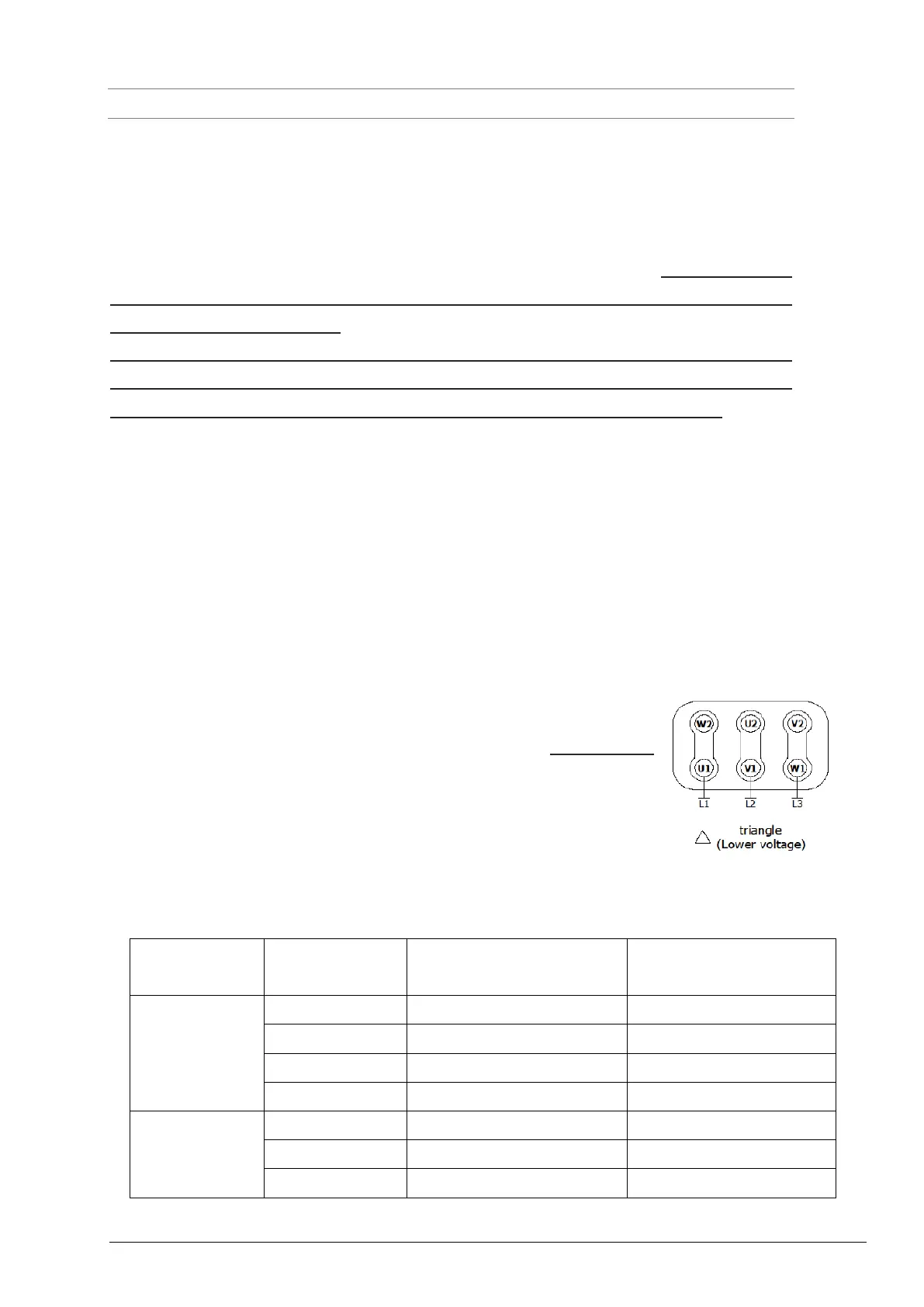
7. Connect the KIT PRO’s output cable to the terminal box of the Black
Line pump’s motor, making sure that the connection is delta (230 V)
like the picture on the side. Refer to the use and maintenance manual
of the Black Line metering pump, chapter 2 paragraph 6, and chapter
8. In the following table please find the information regarding colour
conductors associated to the interconnection of the motor and power
supply. The device shall be connected using this information.
Table 1 Motor and power supply interconnetions
 Loading...