OPERATING INSTRUCTIONS
1. DIAGNOSTICS AND ERROR MESSAGES
Unit self-diagnostics provide fault condition readouts which are described
below:
PROBLEM: LIKELY CAUSE:
Blank display, unit does not (1) Improper battery installation.
power-up. (1) Check battery polarity.
(2) Dead battery.
BAT Annunciator. (1) Low battery voltage, install a new
battery. If problem persists, con-
sult factory.
Display reads OPEN. (1) No thermocouple, RTD or thermis-
tor is plugged into the meter input.
Display reads E1 momentarily. (1) This indicates that an invalid key-
pad entry has been made. Review
keystroke sequence, or consult
manual for input instructions.
Display reads E2 momentarily. (1) Attempt made to activate non-
installed ramp function. NOTE:
RAMP Function enabled on
Models CL25 and CL27 only.
Display reads HI. (1) Meter-mode input-temperature
exceeds rating of selected sensor.
(2) Calibrator-mode keypad-entry
exceeds rating of sensor type.
Display reads LO. (1) Meter-mode input-temperature too
low for accurate measurement.
(2) Calibrator-mode keypad-entry too
low for accurate simulation.
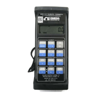
2. INITIAL TURN ON
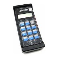
Turn on the instrument by depressing the ON-OFF keyswitch once (Figure
2). At power-up, the unit first performs a display test. All segments and
annunciators of the liquid crystal (LCD) are momentarily turned on for visual
confirmation by the user (Figure 3).
NOTE: In case of missing or poor-contrast segments, contact
factory.
11
 Loading...