61F-GP-N@
4
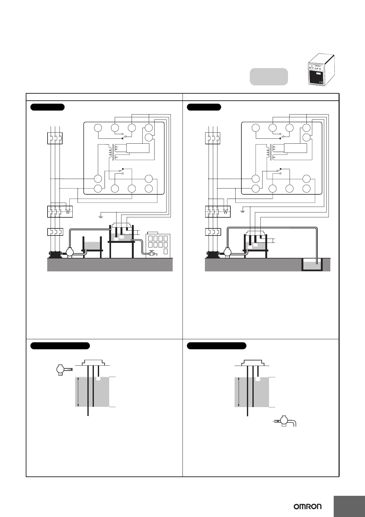
■ Connections
Automatic Water Supply Control Automatic Drainage Control
Compact, Plug-in Type
61F-GP-N
Dimensions:
page 14
Automatic Water Supply and
Drainage Control
Water supply
source
MCCB
RS
M
T
Commercial Voltage
61F-GP-N
PS-3S
Stop
3
9
E2
E3
E1
P
Start
8 V
Power
supply
0 V
U
U
U
24 V
Control
circuit
(See note.)
4
8 765
10 11 1 2
Contac-
tor
Water
tank
Motor
protection
relay
Note: Be sure to ground the common Electrode E3 (the
longest Electrode).
Connection Sockets
PF113A (Front-connecting)
PL11 (Rear-connecting)
Connect terminal 1 to the contactor’s coil terminal.
Note: The power supply depends on the specifications of the
model.
Connections
Reservoir
MCCB
RS
M
T
Commercial Voltage
61F-GP-N
PS-3S
39
E2
E3
E1
P
8 V
0 V
U
U
U
24 V
Control
circuit
(See note.)
4
8 765
10 11 1 2
Start
Stop
Contac-
tor
Power
supply
Motor
protection
relay
Waste-
water
tank
Note: Be sure to ground the common Electrode E3 (the
longest Electrode).
Connection Sockets
PF113A (Front-connecting)
PL11 (Rear-connecting)
Connect terminal 1 to the contactor’s coil terminal.
Note: The power supply depends on the specifications of the
model.
Connections
E1
E2
E3
P
Water
supply
(Indicator ON)
Pump OFF
Pump ON
(Indicator OFF)
The pump stops when the water level reaches E1 (indicator ON)
and starts when the water level drops below E
2 (indicator OFF).
Principles of Operation
E
1
E
2
E
3
Water drainage
(Indicator ON)
Pump OFF
Pump ON
(Indicator OFF)
P
The pump starts when the water level reaches E1 (indicator ON)
and stops when the water level drops below E
2 (indicator OFF).
Principles of Operation
 Loading...