7
61F-GP-N@
Automatic Water Supply Control Automatic Drainage Control
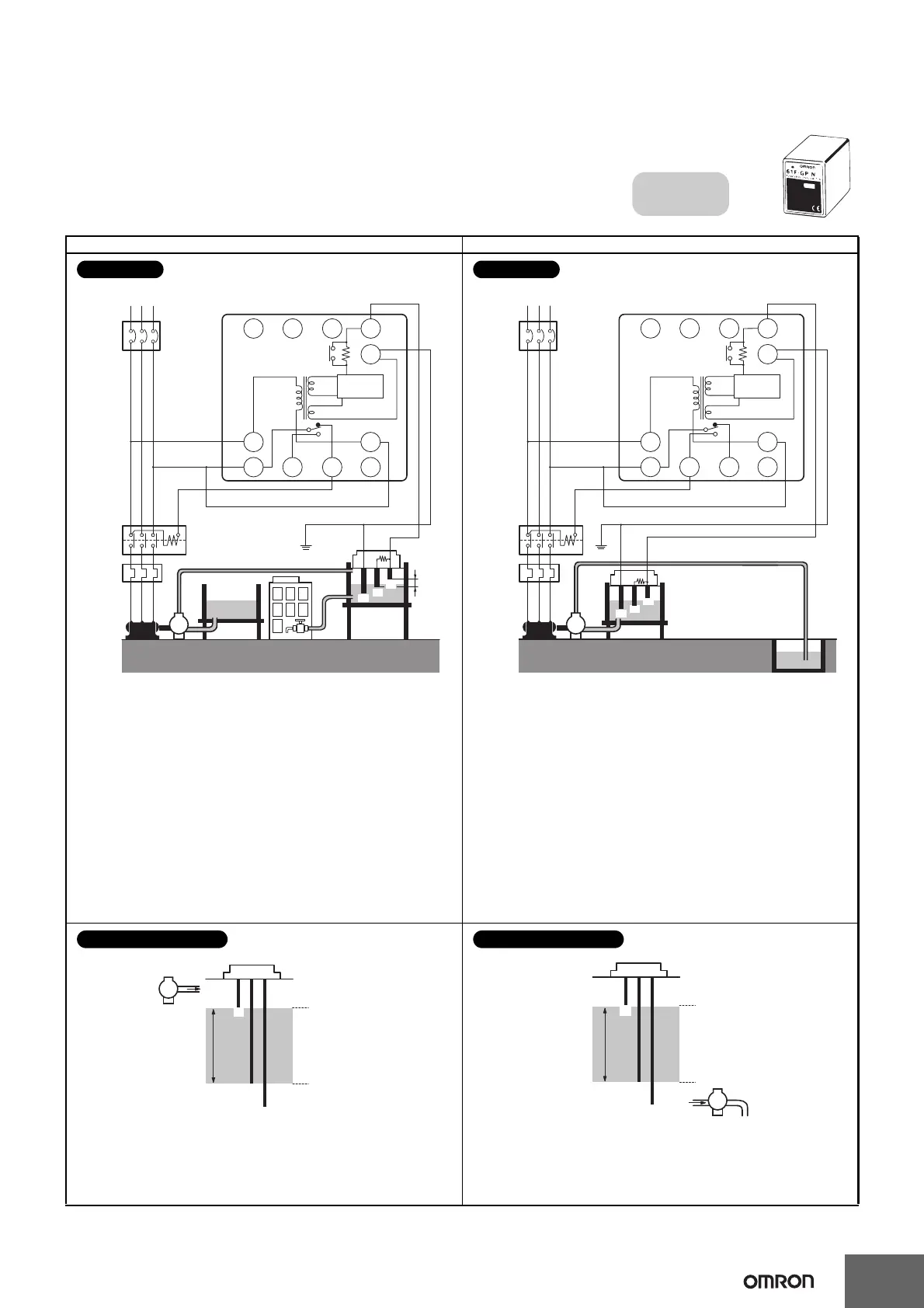
Two-Wire Connections
Automatic Water Supply and Drainage Control
Compact, Plug-in Type
61F-GP-NR
Dimensions:
page 14
E1
E2
E3
U
U
Water supply
source
Stop
Start
MCCB
RS
M
T
Commercial Voltage
61F-GP-NR
(See note.)
5
4
P
8 V
Power
supply
0 V
24 V
PS-3SR
10
3
9
1211
Control
circuit
R
Contac-
tor
Water
tank
Motor
protection
relay
Note: Be sure to ground the common Electrode E3 (the
longest Electrode).
Connection Sockets
PF113 (Front-connecting)
PL11 (Rear-connecting)
• Connect terminal 1 to the contactor’s coil terminal.
Note: The power supply depends on the specifications of the
model.
• With 2-wire connections, only two wires are required between
the 61F-GP-NR and Electrode Holder, but three wires are
required for the Electrodes.
• The Electrode Holder must be specified for 2-wire connections.
(Resistance R is built into Electrode Holders for 2-Wire
Connections.)
Connections
E
1
E
2
U
U
Reservoir
MCCB
RS
M
T
61F-GP-NR
(See note.)
5
4
P
R
8 V
0 V
24 V
PS-3SR
10
3 9
1
2
11
Control
circuit
E
3
Contac-
tor
T
Commercial Voltage
Power
supply
Motor
protection
relay
Waste-
water
tank
Note: Be sure to ground the common Electrode E3 (the
longest Electrode).
Connection Sockets
PF113 (Front-connecting)
PL11 (Rear-connecting)
• Connect terminal 11 to the contactor’s coil terminal.
Note: The power supply depends on the specifications of the
model.
• With 2-wire connections, only two wires are required between
the 61F-GP-NR and Electrode Holder, but three wires are
required for the Electrodes.
• The Electrode Holder must be specified for 2-wire connections.
(Resistance R is built into Electrode Holders for 2-Wire
Connections.)
Connections
E
1
E
2
E
3
P
Water
supply
(Indicator ON)
Pump OFF
Pump ON
(Indicator OFF)
The pump stops when the water level reaches E1 (indicator ON)
and starts when the water level drops below E
2 (indicator OFF).
Principles of Operation
E1
E2
E3
Water drainage
(Indicator ON)
Pump OFF
Pump ON
(Indicator OFF)
P
The pump starts when the water level reaches E1 (indicator ON)
and stops when the water level drops below E
2 (indicator OFF).
Principles of Operation
 Loading...