BN75R/BN150R/BN300R
7
52
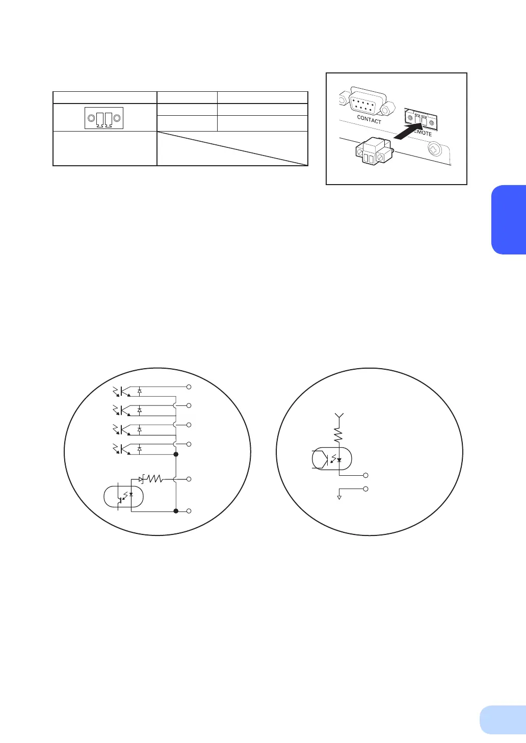
7-4-5. Remote ON/OFF port
Pin assignment Pin number Signal name
1 Remote ON/OFF (+)
2 Remote ON/OFF (-)
Front view
Screw size: Inch screw
#4-40 UNC
7-4-6. Contact Signal ratings
●
Signal output (BL, TR, BU, WB, NBU)
●
UPS Stop Signal input (BS)
Photo coupler ratings Input voltage HIGH(ON) 5 to 12 VDC
Appliable voltage: 35 VDC or less LOW(OFF) 0.7 VDC or less
Maximum current: 20 mA
●
Remote ON/OFF
Voltage between terminals: 10 VDC
Current when closed: max.10 mA
7-4-7. Contact Signal circuit
BL
TR
BU
WB
BS
COM
560Ω2.4V
Remote ON/OFF (+)
Remote ON/OFF (-)
10 V
10kΩ
 Loading...


