7. Using the UPS monitoring software and contact signal
53
Notes
●
When connecting a device such as a relay that generates counter electromotive force to the
signal output circuit, connect diodes that prevent counter electromotive force to both ends of
the relay.
7-4-9. Precautions and notes for the use of the Contact Signal
Explanation
●
When power is restored after the unit stopped automatically during a power failure, the unit
automatically restarts and supplies power. If you do not want to start the connected devices,
turn OFF their switches or disable the auto startup setting after recovery from power failure
(“Setting” - “Boot Settings” - “Auto Reboot” in the menu on the LCD).
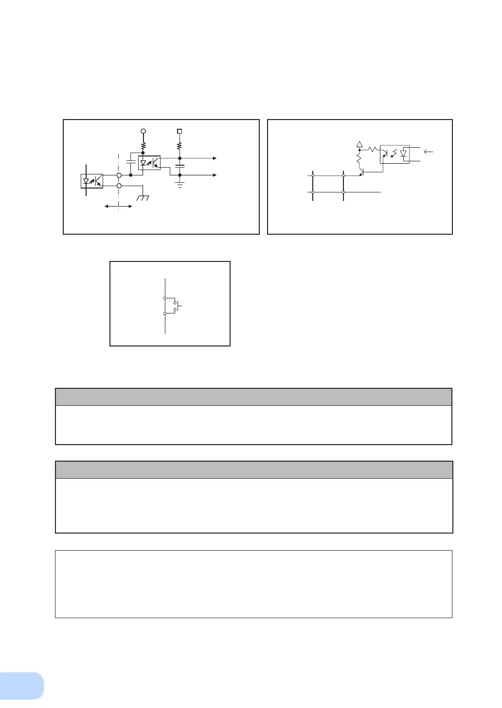
7-4-8. Example of the use of the Contact Signal circuit
●
Example of BU signal output circuit and
the connected circuit
●
Example of BS signal input circuit and the
connected circuit
COM
UPS side
GND
System side
Connecting cable
(twisted or shielded)
BS
12V
1K
1.2K
TLP521
From port on PC
C2458
●
Remote ON/OFF circuit
UPS side
remote ON/OFF
(
+ )
remote ON/OFF
( - )
Example of
remote ON/OFF
To port
on PC
4.7K
TLP521
Inside of
UPS
External
circuit
* C1, C2: 0 pF to several
thousand pF
(Consider the capacity
according to the operating
environment.)
+12V
1KΩ
C2
C1
+5V
A relay output type contact signal card is available for separate purchase.
It can be loaded into the option slot on the back of the UPS.
Visit our website for more details.
(URL: http://www.omron.co.jp/ese/)
• Contact signal card (relay output type) ............. Model number: SC08 (sold separately)
 Loading...


