EasyManuals Logo
Home>Omron>Controller>CJ Series

Omron CJ Series Connection Guide

Omron CJ Series
82 pages
To Next Page IconTo Next Page
To Previous Page IconTo Previous Page
Page #12 background imageLoading...
Page #12 background image
6
Serial Communications Settings
9
6.2. Cable Wiring
For details on cable wiring, refer to SECTION 3 Installation and Wiring of the CJ Series Serial
Communications Units OPERATION MANUAL (Cat. No. W336).
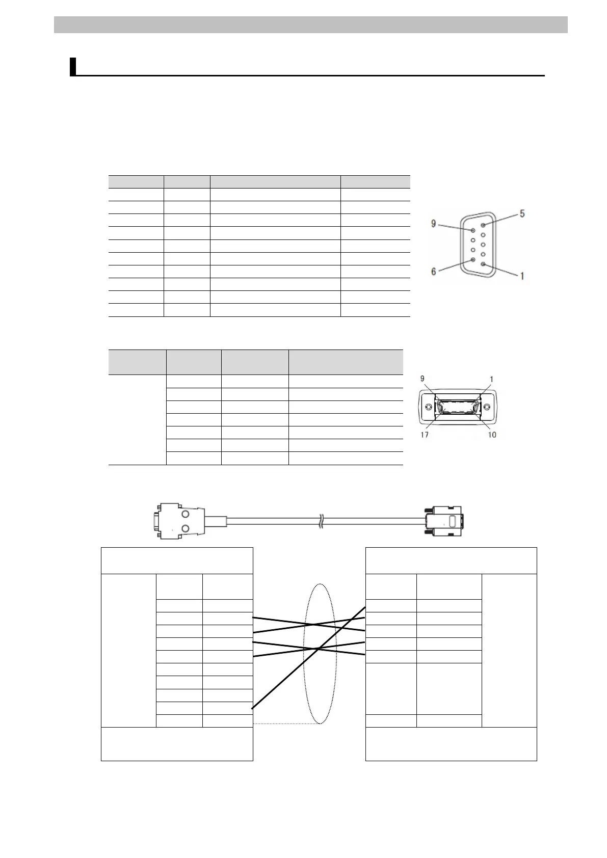
Check connector configuration and pin assignments before wiring.
Connector configuration and pin assignments
CJ1W-SCU42 Serial Communications Unit applicable connector: D-sub 9-pin female
Pin No.
Symbol
Signal name
Input/Output
1
FG
Shield
-
2
SD
Send data
Output
3
RD
Receive data
Input
4
RS
Request to send
Output
5
CS
Clear to send
Input
6
5V
Power supply
-
7
DR
Data set ready
Input
8
ER
Data terminal ready
Output
9
SG
Signal ground
-
Shell
FG
Shield
-
Sensor Controller (ZW-7000) applicable connector: Square 17-pin female
Usage Pin No.
Terminal
name
Function
RS-232C
1
GND(0V)
Signal ground
2
TXD(SD)
Send data
3
RXD(RD)
Receive data
4
RTS(RS)
Request to send
5
CTS(CS)
Clear to send
6 to 17
NC
(Not used)
Shell
FG
Shield
Cable/Pin assignments (RS-232C cable for connecting to PLC: ZW-XPT2)
Serial Communications Unit
(CJ1W-SCU42)
Sensor Controller
(ZW-7000
RS-232C
Interface
Signal
name
Pin No.
Pin No.
Signal
name
RS-232C
Interface
FG
1
1
GND(0V)
SD
2
2
TXD(SD)
RD
3
3
RXD(RD)
RS
4
4
RTS(RS)
CS
5
5
CTS(CS)
5V
6
6 to 17
NC
DR
7
ER
8
SG
9
FG
Shell
Shell
FG
D-sub 9-pin
Connector contact: Male
Square 17-pin
Connector contact: Male

Other manuals for Omron CJ Series

Questions and Answers:

Question and Answer IconNeed help?

Do you have a question about the Omron CJ Series and is the answer not in the manual?

Omron CJ Series Specifications

General IconGeneral
BrandOmron
ModelCJ Series
CategoryController
LanguageEnglish

Related product manuals