27
Basic Concepts Section 2-1
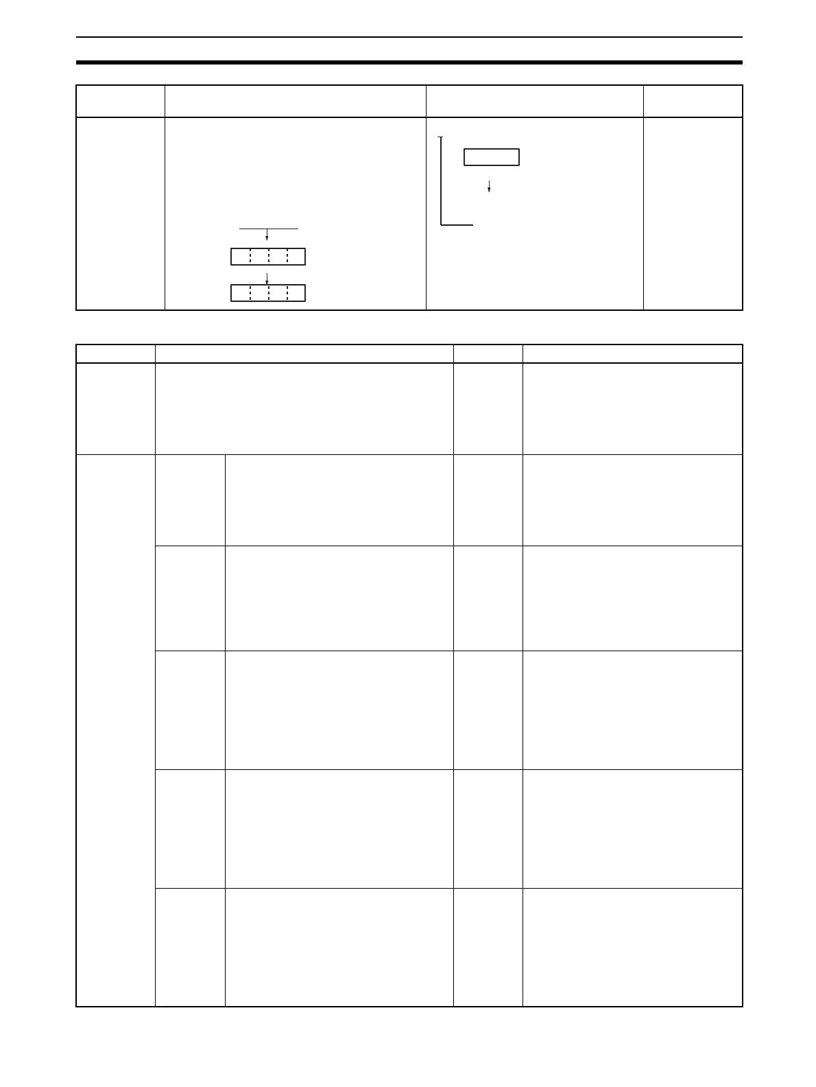
Specifying
indirect DM/
EM addresses
in BCD Mode
MOV #0001
*D00200
Operand Description Notation Application
examples
*D@@@@@
The offset from the beginning of the area is
specified. The contents of the address will be
treated as BCD data (0000 to 9999)to specify
the word address in Data Memory (DM) or Ex-
tended Data Memory (EM). Add an asterisk (*)
at the front to specify an indirect address in
BCD Mode.
Contents
00000 to 9999
(BCD)
D
*D00200
Contents
0 1 0 0
Specifies D0100
Add an asterisk (*).
Operand Description Notation Application examples
Specifying a
register
directly
An index register (IR) or a data register (DR) is speci-
fied directly by specifying IR@ (@: 0 to 15) or DR@
(@: 0 to 15).
IR0
IR1
MOVR 000102 IR0
Stores the PLC memory address for
CIO 0010 in IR0.
MOVR 0010 IR1
Stores the PLC memory address for
CIO 0010 in IR1.
Specifying
an indirect
address
using a reg-
ister
Indirect
address
(No offset)
The bit or word with the PLC memory
address contained in IR@ will be speci-
fied.
Specify ,IR@ to specify bits and words
for instruction operands.
,IR0
,IR1
LD ,IR0
Loads the bit with the PLC memory
address in IR0.
MOV #0001 ,IR1
Stores #0001 in the word with the PLC
memory in IR1.
Constant
offset
The bit or word with the PLC memory
address in IR@ + or – the constant is
specified.
Specify +/– constant ,IR@. Constant off-
sets range from –2048 to +2047 (deci-
mal). The offset is converted to binary
data when the instruction is executed.
+5,IR0
+31,IR1
LD +5 ,IR0
Loads the bit with the PLC memory
address in IR0 + 5.
MOV #0001 +31 ,IR1
Stores #0001 in the word with the PLC
memory address in IR1 + 31
DR offset The bit or word with the PLC memory
address in IR@ + the contents of DR@ is
specified.
Specify DR@ ,IR@. DR (data register)
contents are treated as signed-binary
data. The contents of IR@ will be given a
negative offset if the signed binary value
is negative.
DR0 ,IR0
DR0 ,IR1
LD DR0 ,IR0
Loads the bit with the PLC memory
address in IR0 + the value in DR0.
MOV #0001 DR0 ,IR1
Stores #0001 in the word with the PLC
memory address in IR1 + the value in
DR0.
Auto Incre-
ment
The contents of IR@ is incremented by
+1 or +2 after referencing the value as
an PLC memory address.
+1: Specify ,IR@+
+2: Specify ,IR@ + +
,IR0 ++
,IR1 +
LD ,IR0 ++
Increments the contents of IR0 by 2
after the bit with the PLC memory
address in IR0 is loaded.
MOV #0001 ,IR1 +
Increments the contents of IR1 by 1
after #0001 is stored in the word with
the PLC memory address in IR1.
Auto Dec-
rement
The contents of IR@ is decremented by
–1 or –2 after referencing the value as
an PLC memory address.
–1: Specify ,–IR@
–2: Specify ,– –IR@
,– –IR0
,–IR1
LD ,– –IR0
After decrementing the contents of IR0
by 2, the bit with the PLC memory
address in IR0 is loaded.
MOV #0001 ,–IR1
After decrementing the contents of IR1
by 1, #0001 is stored in the word with
the PLC memory address in IR1.