98
Wiring Section 3-4
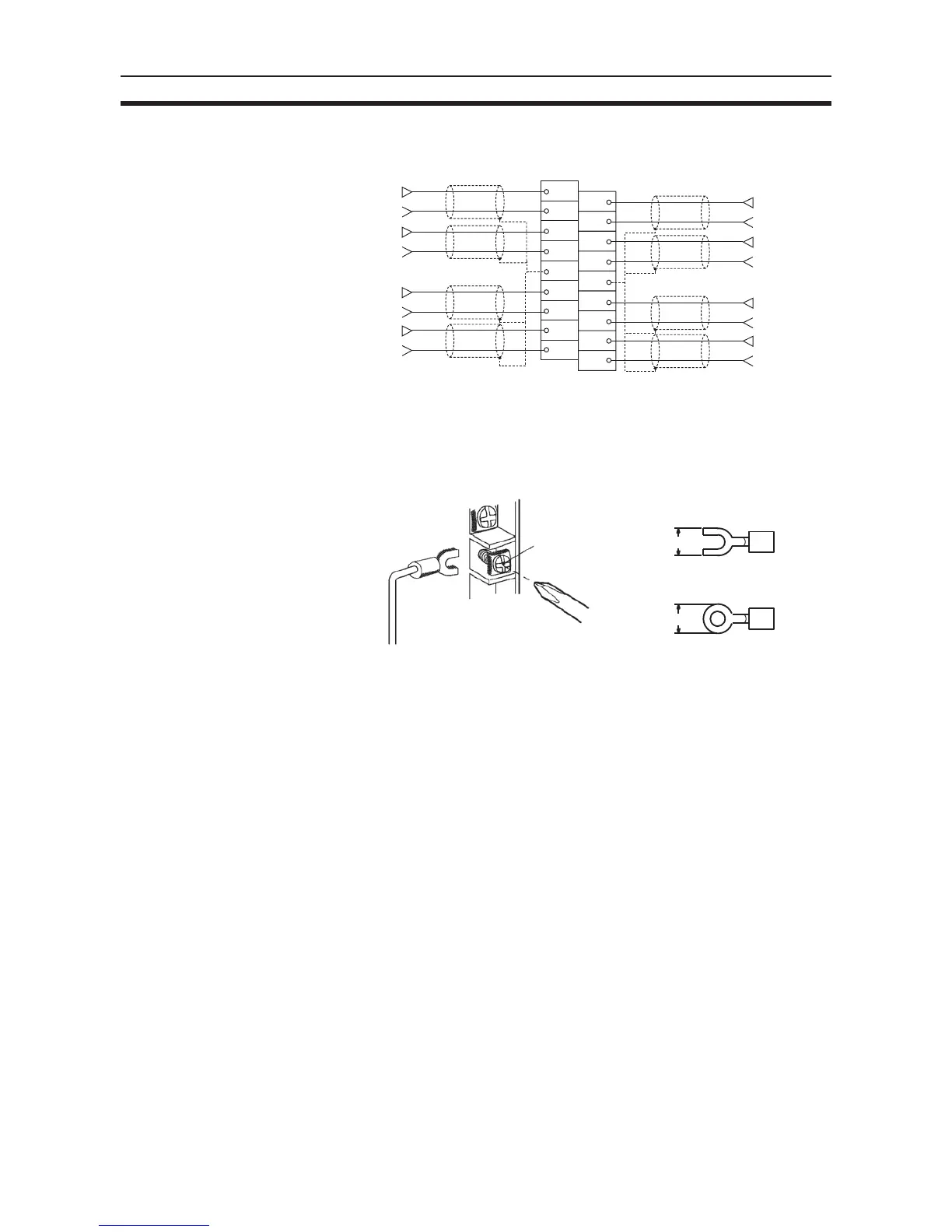
3-4-4 Input Wiring Example
Note Crimp-type terminals must be used for terminal connections, and the screws
must be tightened securely. Use M3 screws and tighten them to a torque of
0.5 N·m.
Note 1. When using current inputs, turn ON the voltage/current switches. Refer to
3-3-4 Voltage/Current Switch for further details.
2. For inputs that are not used, either set to “0: Not used” in the input number
settings (refer to 3-6-1 Input Settings and Conversion Values) or short-cir-
cuit the voltage input terminals (V+) and (V–). If this is not performed and
the inputs are set for the 1 to 5-V or 4 to 20-mA range, the Line Disconnec-
tion Flag will turn ON.
3. When connecting the shield of the analog input cables* to the Unit’s AG ter-
minals, as shown in the above diagram, use a wire that is 30 cm max. in
length if possible.
!Caution Do not connect anything to N.C. terminals shown in the wiring diagram on
page 95.
Connect the analog input line shield to the AG terminal on the Analog Input
Unit to improve noise resistance.
3-4-5 Input Wiring Considerations
When wiring inputs, apply the following points to avoid noise interference and
optimize Analog Input Unit performance.
• Use two-core shielded twisted-pair cables for input connections.
B1
B3
B2
B4
B5
B6
B7
B8
B9
A1
A3
A2
A4
A5
A6
A7
A8
A9
+
−
Input 2
+
−
Input 4
+
−
Input 6
+
−
Input 8
+
−
Input 1
+
−
Input

 Loading...


