94
Components and Switch Settings Section 3-3
Note The operation mode can also be set using bits 00 to 07 of DM word m+18, in
addition to the hardware operation mode switch. The contents of DM word
m+18 are shown below
.
m = D20000 + (unit number x 100)
Relationship between Operation Mode Setting and Hardware Operation
Mode Switch
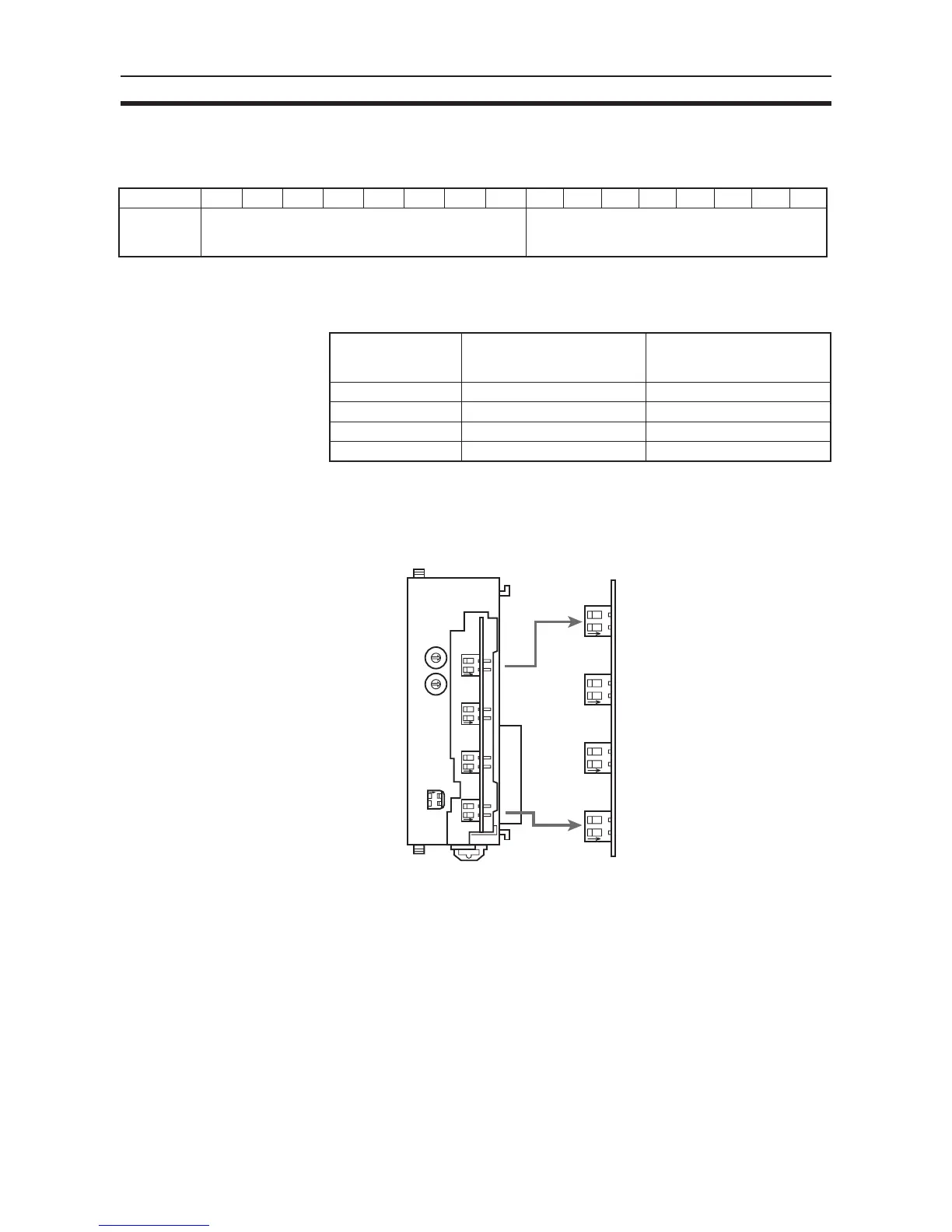
3-3-4 Voltage/Current Switch
The analog conversion input can be switched from voltage input to current
input by changing the pin settings on the voltage/current switch located on the
back of the terminal block.
Note There are only four inputs for the CJ1W-AD041-V1.
!Caution Be sure to turn OFF the power to the PLC before mounting or removing the
terminal block.
Bit 15 14 13 12 11 10 09 08 0706050403020100
D (m+18) Conversion period/resolution setting Operation mode setting
00: Normal mode
C1: Adjustment mode
Hardware operation
mode switch
Setting of bits 00 to 07 of
m+18
Operation mode when
power is turned ON or Unit
is restarted
Normal mode Normal mode Normal mode
Normal mode Adjustment mode Adjustment mode
Adjustment mode Normal mode Adjustment mode
Normal mode Adjustment mode Adjustment mode
MACH
No
.
AD081
RUN
ERC
ERH
B1 A1
ADJ
x10
1
x10
0
21212121
0
9
8
7
6
5
4
3
2
1
0
9
8
7
6
5
4
3
2
1
ONONONON
21212121
ONONONON
O
N
12
MODE
OFF: Voltage input
ON: Current input
Input 2
Input 1
Input 4
Input 3
Input 6
Input 5
Input 8
Input 7

 Loading...


