103
Exchanging Data with the CPU Unit Section 3-5
Set Values and Stored Values
Note 1. The input signal range of “1 to 5 V” and “4 to 20 mA” is switched using the
pins of the voltage/current switch. Refer to 3-3-4 Voltage/Current Switch for
details.
2. The default of mean value processing setting is set to “Mean value pro-
cessing with 2 buffers.” Refer to 3-6-3 Mean Value Processing.
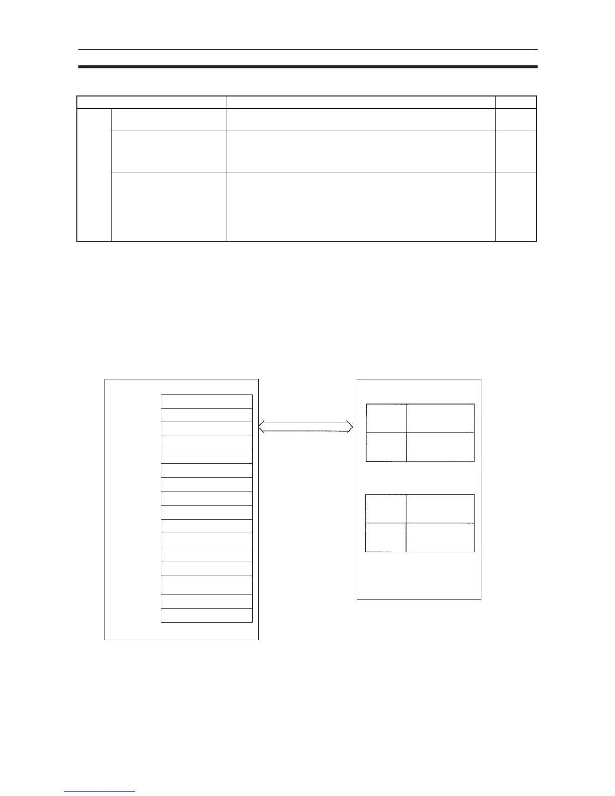
3-5-5 I/O Refresh Data Allocations
I/O refresh data for the Analog Input Unit is exchanged according to the allo-
cations in the Special I/O Unit Area.
Note 1. The words in the Special I/O Unit Area in the CIO Area that are allocated
to the Analog Input Unit are determined by the setting of the unit number
switches on the front panel of the Unit. Refer to 3-5-2 Unit Number Setting
for details on the method used to set the unit number switches.
Item Contents Page
Input Use setting 0: Not used.
1: Used.
106
Input signal range 00: –10 to 10 V
01: 0 to 10 V
10: 1 to 5 V/4 to 20 mA (See note 1.)
11: 0 to 5 V
107
Mean value processing set-
ting
0000: Mean value processing with 2 buffers (See note 3.)
0001: Mean value processing not used
0002: Mean value processing with 4 buffers
0003: Mean value processing with 8 buffers
0004: Mean value processing with 16 buffers
0005: Mean value processing with 32 buffers
0006: Mean value processing with 64 buffers
109
CIO n
CIO 2030 to CIO 2039
CIO 2040 to CIO 2049
CIO 2050 to CIO 2059
CIO 2000 to CIO 2009
CIO 2010 to CIO 2019
CIO 2020 to CIO 2029
CIO 2090 to CIO 2099
CIO 2060 to CIO 2069
CIO 2070 to CIO 2079
CIO 2080 to CIO 2089
SYSMAC CJ-series CPU Unit CJ1W-AD041-V1/081-V1 Analog Input Unit
IN refresh
(I/O Refresh Data Area)
Unit #0
Unit #1
Unit #2
Unit #3
Unit #4
Unit #5
Unit #6
Unit #7
Unit #8
Unit #9
(Special I/O Unit Area)
OUT refresh
Allocated words
CIO 2950 to CIO 2959
CIO 2100 to CIO 2109
Unit #10
Unit #n
Unit #95
Normal mode
IN refresh
OUT refresh
Adjustment mode
n = 2000 + (unit number × 10)
I/O refresh
CIO 2000 + (n × 10) to
CIO 2000 + (n × 10) + 9
At the I/O refresh by the
PLC, outputs (CPU to
Unit) and inputs (Unit to
CPU) are refreshed in
order with every cycle.
CIO n + 1
to
CIO n + 9
CIO n to
CIO n + 7
CIO n + 8
to
CIO n + 9
to
to
to
to

 Loading...


