EasyManua.ls Logo

Omron CPM1A User Manual

Omron CPM1A
201 pages
To Next Page IconTo Next Page
To Previous Page IconTo Previous Page
Page #139 background image
116
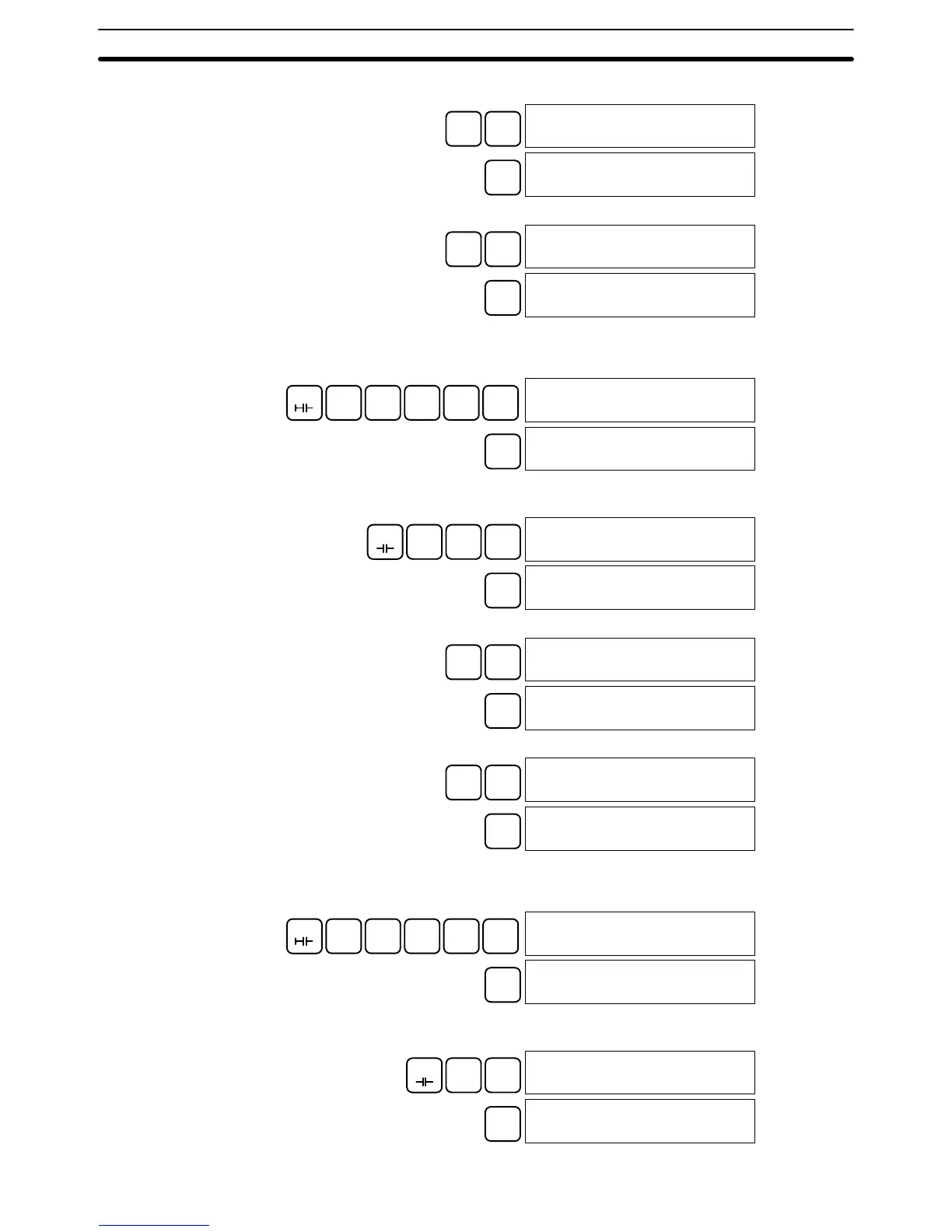
3. Input the 1-second timer T001.
TIM
B
1
00006
TIM 001
WRITE
00006 TIM DATA
#0000
4. Input the SV for T001 (#0010 = 1.0 s).
B
1
A
0
00006 TIM DATA
#0010
WRITE
00007READ
NOP (000)
The following key operations are used to input the 2-second timer.
1, 2, 3... 1. Input the normally open condition IR 20000.
LD
C
2
A
0
A
0
A
0
A
0
00007
LD 20000
WRITE
00008READ
NOP (000)
2. Input the normally closed AND condition T002.
(It isn’t necessary to input leading zeroes.)
AND
NOT TIM
C
2
00008
AND NOT TIM 002
WRITE
00009READ
NOP (000)
3. Input the 2-second timer T002.
TIM
C
2
00009
TIM 002
WRITE
00009 TIM DATA
#0000
4. Input the SV for T002 (#0020 = 2.0 s).
C
2
A
0
00009 TIM DATA
#0020
WRITE
00010READ
NOP (000)
The following key operations are used to input the 10-count counter.
1, 2, 3... 1. Input the normally open condition IR 20000.
LD
C
2
A
0
A
0
A
0
A
0
00010
LD 20000
WRITE
00011READ
NOP (000)
2. Input the normally open AND condition T001.
(It isn’t necessary to input leading zeroes.)
AND
TIM
B
1
00011
AND TIM 001
WRITE
00012READ
NOP (000)
(3) Inputting the
Two-second Timer
(4) Inputting the 10-count
Counter
Programming Example
Section 4-4

Table of Contents

Other manuals for Omron CPM1A

Question and Answer IconNeed help?

Do you have a question about the Omron CPM1A and is the answer not in the manual?

Omron CPM1A Specifications

General IconGeneral
ModelCPM1A
TypeCompact PLC
Communication PortsRS-232C (optional)
Instruction SetBasic and advanced instructions
Operating Temperature0 to 55°C
Storage Temperature-20 to 75°C
Humidity10% to 90% RH (non-condensing)
Power Supply24 VDC or 100-240 VAC
ExpansionExpansion I/O units available
Timers128
Counters256 counters
I/O Points10, 20, 30, or 40 points (depending on model)

Summary

Application Considerations

PRECAUTIONS

Safety Precautions

Details critical safety warnings for handling PC units, power, and external circuits.

Operating Environment Precautions

Advises on suitable locations and environmental conditions for PC operation to ensure longevity.

SECTION 1 Introduction

CPM1A Features and Functions

Describes the CPM1A's key features, I/O capacity, input/output functions, and communication capabilities.

SECTION 2 Unit Specifications and Components

Specifications

Provides general, I/O, and communications adapter specifications for CPM1A units.

Unit Components

Identifies and describes components of CPU, Expansion I/O, Analog, Sensor, CompoBus/S, DeviceNet, and Adapter units.

SECTION 3 Installation and Wiring

Design Precautions

Covers essential precautions for designing a CPM1A system, including power wiring and interlocks.

CPM1A Installation and Expansion Unit Connection

Details CPM1A orientation, mounting, and connecting expansion units correctly.

Wiring and Connections

Provides guidelines and diagrams for power, input, output, and communication wiring.

SECTION 4 Using Peripheral Devices

SECTION 5 Test Runs and Error Processing

Initial System Checks and Test Run Procedure

Guides on initial system checks and the CPM1A test run process.

Error Handling and Troubleshooting

Details error messages, programming errors, and troubleshooting flowcharts.

SECTION 6 Expansion Memory Unit

Related product manuals