72
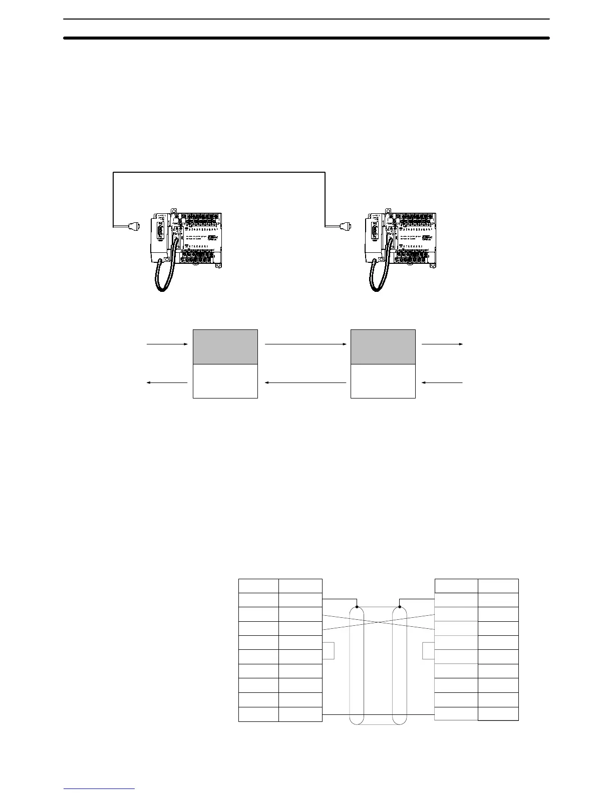
3-4-8 One-to-one PC Link Connections
A CPM1A can be linked to a CPM1A, CQM1, CPM1, CPM2A, CPM2C,
SRM1(-V2), C200HS or C200HX/HG/HE PC through an RS-232C Adapter. One
PC acts as the Master and the other as the Slave to link up to 256 bits in the LR
area (LR 0000 to LR 1515).
CPM1A CPU Unit
RS-232C Adapter
(see note)
CPM1A CPU Unit
RS-232C Cable
RS-232C Adapter
(see note)
Link bits
WRITE area
READ area
LR 00
LR 07
LR 08
LR 15
WRITE
READ
READ area
WRITE area
LR 00
LR 07
LR 08
LR 15
READ
WRITE
Link bits
Note One-to-one PC connections can only be used when the RS-232C Adapter
(CPM1-CIF01) is connected.
Set the DIP switch of the RS-232C Adapter (CPM1-CIF01) to the NT (bottom)
side.
The following diagram shows the wiring in the RS-232C cable used to connect a
CPM1A to another PC.
1/Cover
2
3
4
5
6
SD
RD
RS
CS
–
–
–
SG
7
8
9
1/Cover
2
3
4
5
6
7
8
9
FG
SD
RD
RS
CS
–
–
SG
9
RS-232C Adapter
Pin No.Signal
–
Pin No. Signal
RS-232C Adapter
FG
Wiring and Connections
Section 3-4

 Loading...


