EasyManua.ls Logo

Omron CPM1A User Manual

Omron CPM1A
201 pages
To Next Page IconTo Next Page
To Previous Page IconTo Previous Page
Page #94 background image
71
The following diagram shows the wiring in the RS-422 cables used to connect
CPM1A PCs to a 3G2A9-AL004-E Link Adapter. In both the Link Adapter/
RS-422 Adapter connections and the RS-422 Adapter/RS-422 Adapter connec-
tions, connect the SG, RDA, RDB, SDA, and SDB terminals to the same termi-
nals in the other Adapter.
25-pin D-sub Connector
Use a straight RS-232C
cable to connect to the
host computer’s
RS-232C port.
9-pin D-sub Connector
Signal
Pin no.
1
2
3
4
5
6
7
8
9
RDB
SG
SDB
RDA
FG
SDA
3G2A9-AL004-E Link Adapter
RS-422 Adapter
SG
RDA
RDB
SDA
SDB
CPM1A CPU Unit
Note 1. The maximum length of the RS-422 cable should be 500 m.
2. Set the termination resistance switch to “ON” (upper side) for Adapters on
both ends of the Host Link system.
Always use crimp connectors when wiring the RS-422 Adapters. Use M3 termi-
nal screws and tighten the screws securely to the torque of 0.5 N m.
6.2 mm max.
Fork terminal
6.2 mm max.
Ring terminal
Wiring and Connections
Section 3-4

Table of Contents

Other manuals for Omron CPM1A

Question and Answer IconNeed help?

Do you have a question about the Omron CPM1A and is the answer not in the manual?

Omron CPM1A Specifications

General IconGeneral
ModelCPM1A
TypeCompact PLC
Communication PortsRS-232C (optional)
Instruction SetBasic and advanced instructions
Operating Temperature0 to 55°C
Storage Temperature-20 to 75°C
Humidity10% to 90% RH (non-condensing)
Power Supply24 VDC or 100-240 VAC
ExpansionExpansion I/O units available
Timers128
Counters256 counters
I/O Points10, 20, 30, or 40 points (depending on model)

Summary

Application Considerations

PRECAUTIONS

Safety Precautions

Details critical safety warnings for handling PC units, power, and external circuits.

Operating Environment Precautions

Advises on suitable locations and environmental conditions for PC operation to ensure longevity.

SECTION 1 Introduction

CPM1A Features and Functions

Describes the CPM1A's key features, I/O capacity, input/output functions, and communication capabilities.

SECTION 2 Unit Specifications and Components

Specifications

Provides general, I/O, and communications adapter specifications for CPM1A units.

Unit Components

Identifies and describes components of CPU, Expansion I/O, Analog, Sensor, CompoBus/S, DeviceNet, and Adapter units.

SECTION 3 Installation and Wiring

Design Precautions

Covers essential precautions for designing a CPM1A system, including power wiring and interlocks.

CPM1A Installation and Expansion Unit Connection

Details CPM1A orientation, mounting, and connecting expansion units correctly.

Wiring and Connections

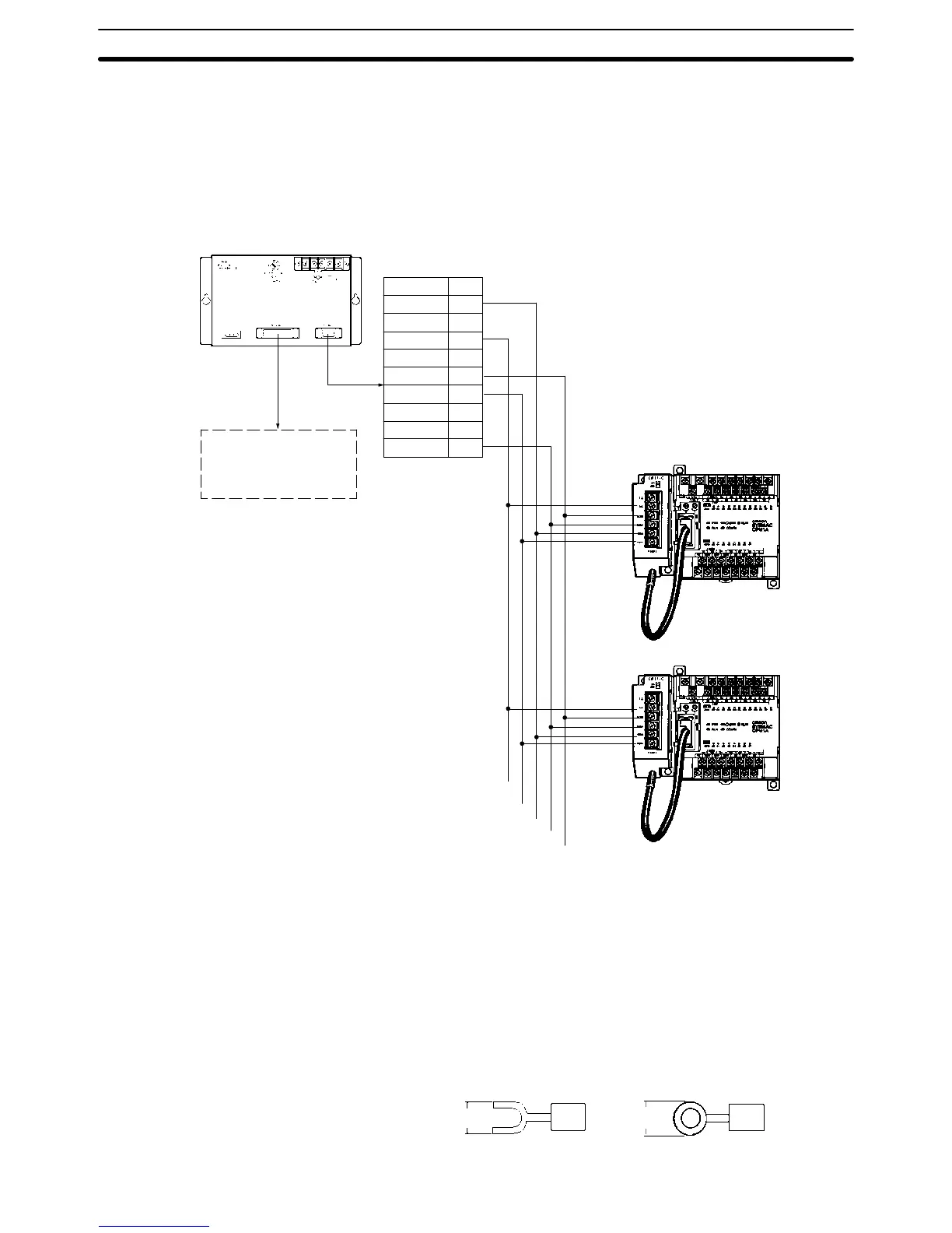
Provides guidelines and diagrams for power, input, output, and communication wiring.

SECTION 4 Using Peripheral Devices

SECTION 5 Test Runs and Error Processing

Initial System Checks and Test Run Procedure

Guides on initial system checks and the CPM1A test run process.

Error Handling and Troubleshooting

Details error messages, programming errors, and troubleshooting flowcharts.

SECTION 6 Expansion Memory Unit

Related product manuals