23
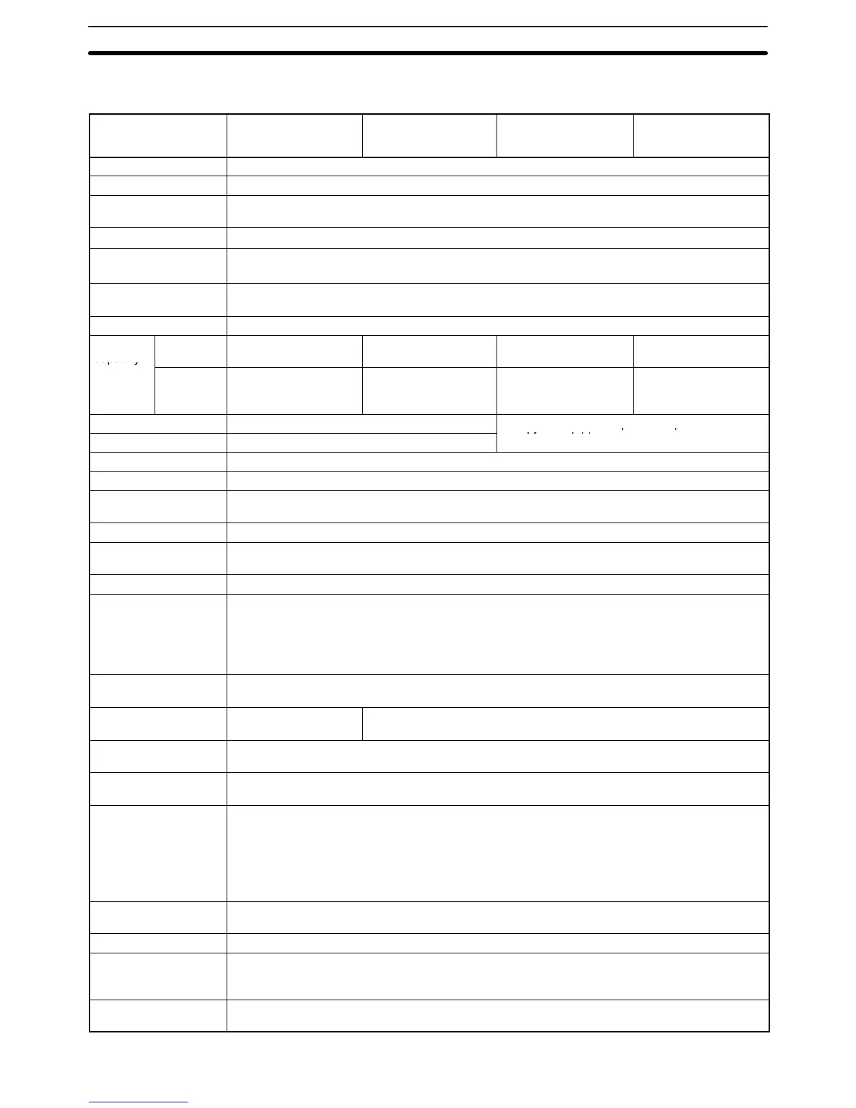
2-1-2 Characteristics
Item
CPM1A-10CDR-(-V1)
CPM1A-10CDT-(-V1)
CPM1A-10CDT1-(-V1)
CPM1A-20CDR-(-V1)
CPM1A-20CDT-(-V1)
CPM1A-20CDT1-(-V1)
CPM1A-30CDR-(-V1)
CPM1A-30CDT-(-V1)
CPM1A-30CDT1-(-V1)
CPM1A-40CDR-(-V1)
CPM1A-40CDT-(-V1)
CPM1A-40CDT1-(-V1)
Control method Stored program method
I/O control method Cyclic scan with direct output; immediate refresh processing
Programming
language
Ladder diagram
Instruction length
1 step per instruction, 1 to 5 words per instruction
Types of instructions
Basic instructions: 14
Special instructions: 77 types, 135 instructions
Execution time Basic instructions: 0.72 to 16.2 µs
Special instructions: 16.3 µs (MOV instruction)
Program capacity 2,048 words
Max. I/O
capacity
CPU Unit
only
10 points 20 points 30 points 40 points
used for work bits.
Work bits 512 bits: 20000 to 23115 (Words IR 200 to IR 231)
Special bits (SR area) 384 bits: 23200 to 25515 (Words IR 232 to IR 255)
Temporary bits (TR
area)
8 bits (TR0 to TR7)
Holding bits (HR area) 320 bits: HR 0000 to HR 1915 (Words HR 00 to HR 19)
Auxiliary bits (AR
area)
256 bits: AR 0000 to AR 1515 (Words AR 00 to AR 15)
Link bits (LR area) 256 bits: LR 0000 to LR 1515 (Words LR 00 to LR 15)
Timers/Counters 128 timers/counters (TIM/CNT 000 to TIM/CNT 127)
100-ms timers: TIM 000 to TIM 127
10-ms timers (high-speed counter): TIM 000 to TIM 127 (see note 1)
(the timer numbers used are the same as for the 100-ms timers)
Decrementing counters and reversible counters
Data memory Read/Write: 1,024 words (DM 0000 to DM 1023)
Read-only: 512 words (DM 6144 to DM 6655)
Interrupt processing
(see note 2)
External interrupts: 2 External interrupts: 4
Interval timer
interrupts
1 (0.5 to 319,968 ms in Scheduled Interrupt Mode or Single Interrupt Mode)
Memory protection HR and read/write DM area contents; and counter values maintained during power
interruptions.
Memory backup Flash memory:
The program, read-only DM area, and PC Setup area are backed up without a battery.
Capacitor backup:
The read/write DM area, error log area, HR area, and counter values are backed up by a
capacitor for 20 days at 25C. The capacitor backup time depends on the ambient
temperature. See the graph on the following page for details.
Self-diagnostic
functions
CPU Unit failure (watchdog timer), I/O bus error, and memory failure
Program checks No END instruction, programming errors (continuously checked during operation)
High-speed counter One high-speed counter: 5 kHz single-phase or 2.5 kHz two-phase (linear count method)
Increment mode: 0 to 65,535 (16 bits)
Up/Down mode: –32,767 to 32,767 (16 bits)
Quick-response inputs The same inputs are used for quick-response inputs and external interrupt inputs.
(Min. input pulse width: 0.2 ms)
Specifications Section 2-1

 Loading...


