!
34
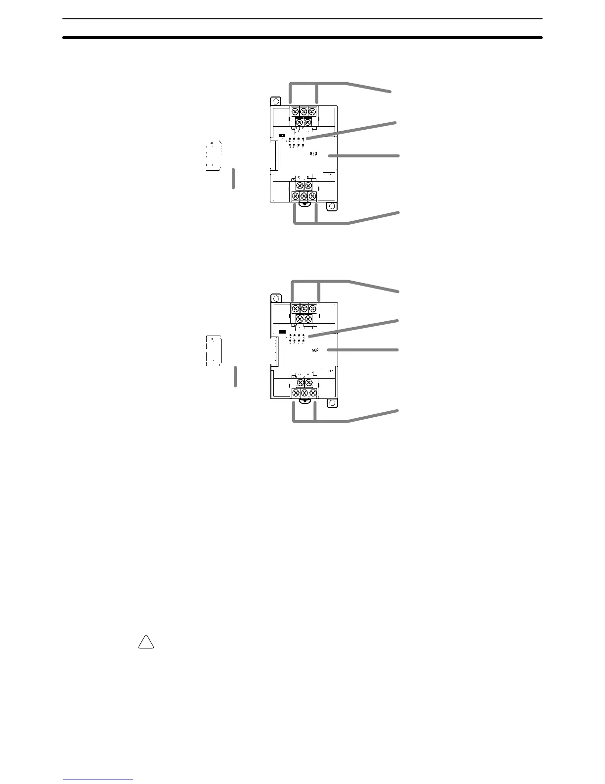
Expansion I/O Unit with 8 Input Terminals
1. Input terminals
5. Expansion I/O Unit Connecting Cable
3. Input indicators
6. Expansion connector
1. Input terminals
Expansion I/O Unit with 8 Output Terminals
5. Expansion I/O Unit Connecting Cable
6. Expansion connector
4. Output indicators
2. Output terminals
2. Output terminals
1, 2, 3... 1. Input Terminals
Connects the Unit to external input devices.
2. Output Terminals
Connects the Unit to external output devices.
3. Input Indicators
The input indicators are lit when the corresponding input terminal is ON.
4. Output Indicators
The output indicators are lit when the corresponding output terminal is ON.
5. Expansion I/O Unit Connecting Cable
Connects the Expansion I/O Unit to the Expansion Connector on the PC’s
CPU Unit or another Expansion Unit.
Caution Do not touch the Expansion I/O Unit Connecting Cable while the power is being
supplied in order to prevent any malfunction due to static electricity.
6. Expansion Connector
Connects to another Expansion Unit (Expansion I/O Unit, Analog I/O Unit, or
CompoBus/S I/O Link Unit). Up to 3 Expansion Units can be connected to a
CPU Unit.
Unit Components
Section 2-2

 Loading...


