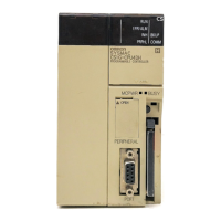
CS/CJ Series HOST Link Driver
GP-Pro EX Device/PLC Connection Manual
23
Setting of External Device
For communication settings of the communication unit, you need to register the serial communication unit to be
used by the ladder software in advance.
After registration, open [I/O Table] of the ladder software. Click [Switch] from the menu displayed by right-
clicking [Serial Communication Unit] and set as below.
Notes
• Do not set the duplicate node address in the same network address group.
Setup Items Settings
WIRE (2wire/4wire switch)
*1
*1 Use the WIRE switch on the front of the Controller Link unit to set.
4wire
TERM (Termination resistance switch)
*2
*2 Use the TERM switch on the front of the Controller Link unit to set. For 1:n connection, set only the station that
serves as termination resistance to ON.
ON
Line Speed 19200
Parameter 1,7,2,E
Mode Default (HOST Link)
Send Delay Time 0
CS Control None
Unit No. Setting Rotary Switch
*3
*3 You need to set this switch to the same value as "CPU High Function Unit No." of the serial communication
unit in the I/O table assigned by the ladder tool.
Same value as "CPU High Function Unit No."
Unit No. Option
Source Network Address
*4
*4 Parameter used when you access beyond network. Set in the routing table of "CX-Net Network Configuration".
Please refer to the manual of the External Device for more details.
Option
Node Address Setting Rotary Switch
*5
*5 Parameter used when you access beyond network. Set with the rotary switch on the front of the Controller Link
unit used for access beyond network.
Option

 Loading...