CS/CJ Series HOST Link Driver
GP-Pro EX Device/PLC Connection Manual
29
5 Cable Diagram
The cable diagram shown below may be different from the cable diagram recommended by OMRON
Corporation. Please be assured there is no operational problem in applying the cable diagram shown in this
manual.
• The FG pin of the main body of the External Device must be D-class grounded. Please refer to the manual of
the External Device for more details.
• SG and FG are connected inside the Display. When connecting SG to the External Device, design the system
not to form short-circuit loop.
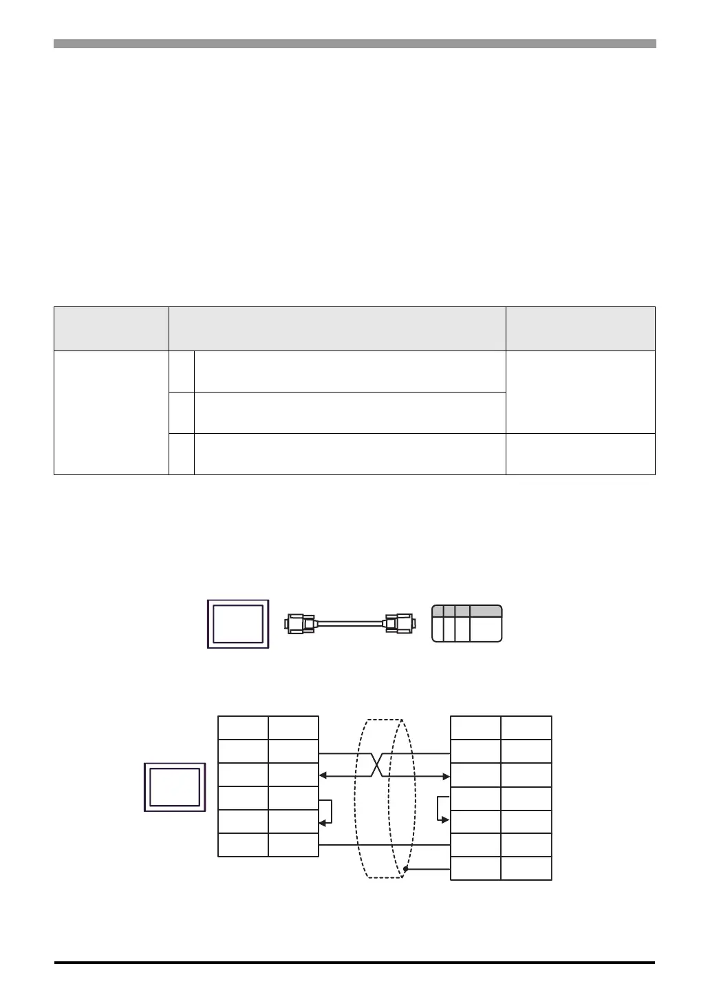
Cable Diagram 1
A) When using OMRON SYSMAC link cable (CA3-CBLSYS-01) by Pro-face
B) When using XW2Z-200S-V or XW2Z-500S-V by OMRON Corporation
C) When using your own cable
Display
(Connection Port)
Cable Notes
GP (COM1)
A
OMRON SYSMAC link cable by Pro-face
CA3-CBLSYS-01 (5m)
B
XW2Z-200S-V (2m) or XW2Z-500S-V (5m)
by OMRON Corporation
C Your own cable
The cable length must be
15m or less.
Display
External
Device
CA3-CBLSYS-01
or
XW2Z-200S-V
or
XW2Z-500S-V
Display
D-sub 9 pin (socket)
Pin
Signal
name
Shield
External Device
D-sub 9 pin (socket)
Pin
Signal
name
SD
RD
RS
CS
SG
3
2
7
8
5
2
3
4
5
9
1
SD
RD
RS
CS
SG
FG

 Loading...