E5jJ
E5jJ
Heater
+
–
200 VAC
14
13
12
11
7
6
9
8
10
5
4
1
3
2
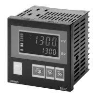
Heater burnout and
temperature alarm
Alarm output 1
Control output
E5CJ-H
Note: 1. Alarm
1 is used as heater burnout alarm and temperature alarm
for
models incorporating a heater burnout alarm.
2. Wire
through the hole of the Current T
ransformer
. The Current
Transformer
and the T
emperature Controller can be connected
regardless
of polarity
.
(see
note 2)
(see note 1)
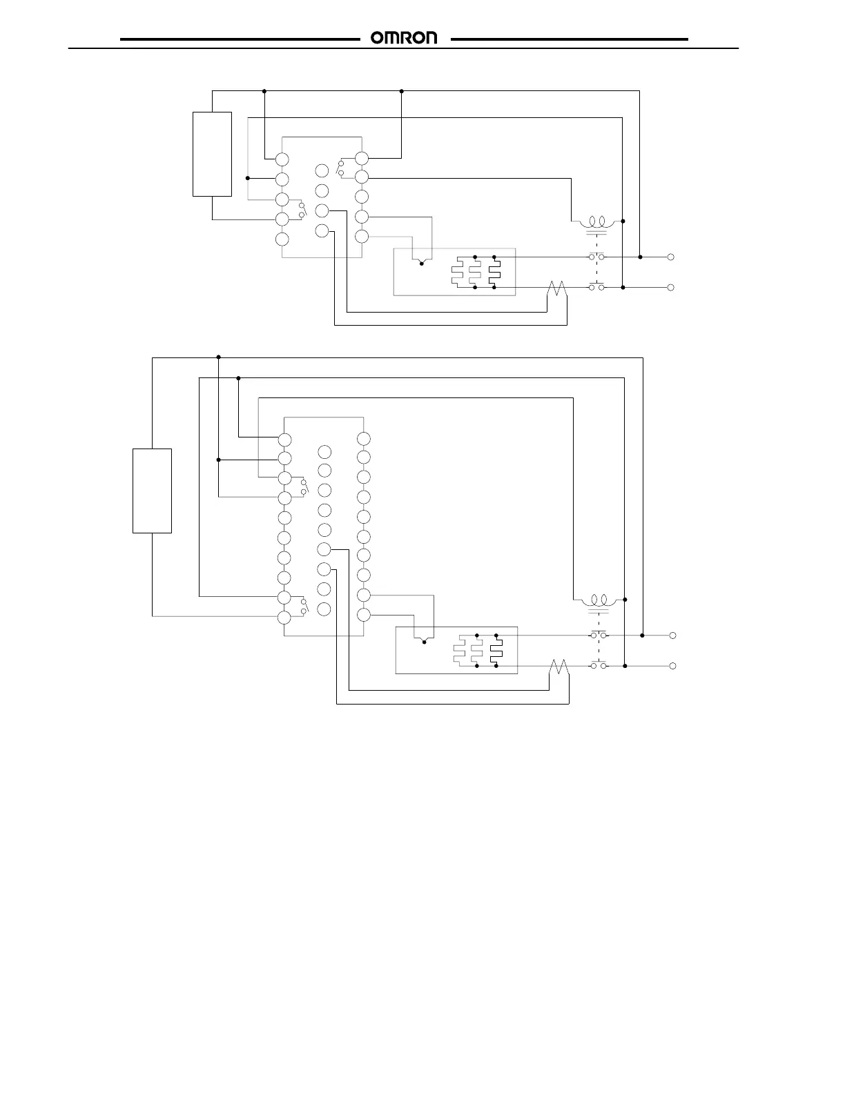
E5CJ-H
E5EJ-H
Heater
+
–
200 VAC
24
23
22
21
12
11
14
13
15
E5EJ-H
17
16
19
18
20
26
25
28
27
29
5
4
1
3
2
7
6
9
8
10
Alarm output 1
Heater burnout and
temperature alarm
(see note 1)
(see note 2)
Control output
CT
•
Set the alarm mode selector 1 to 0 (i.e., no alarm function is ON)
so
that alarm output 1 will output only heater burnout alarms.
• If the difference in current is small, increase the apparent
electrical
current by increasing the number of turns of the heater
wire
around the CT
. The current displayed by the heater current
value display increases in proportion to the number of turns of
the
heater wire.
• Use
the K2CU-F
jjA-j
GS (incorporating gate input terminals)
for
detecting three-phase heater burnout.
Output Retention Reset
Once
the heater burnout alarm detects heater burnout, alarm output
1 will turn ON. To turn OFF alarm output 1, set the heater burnout
alarm
value to 0.0 A or turn of
f the T
emperature Controller and then
turn
on the T
emperature Controller
.
 Loading...