E5jJ
E5jJ
7
Operation
NOTICE: Always turn of
f the power supply to the T
emperature Controller before changing any switch settings.
Settings
E5CJ
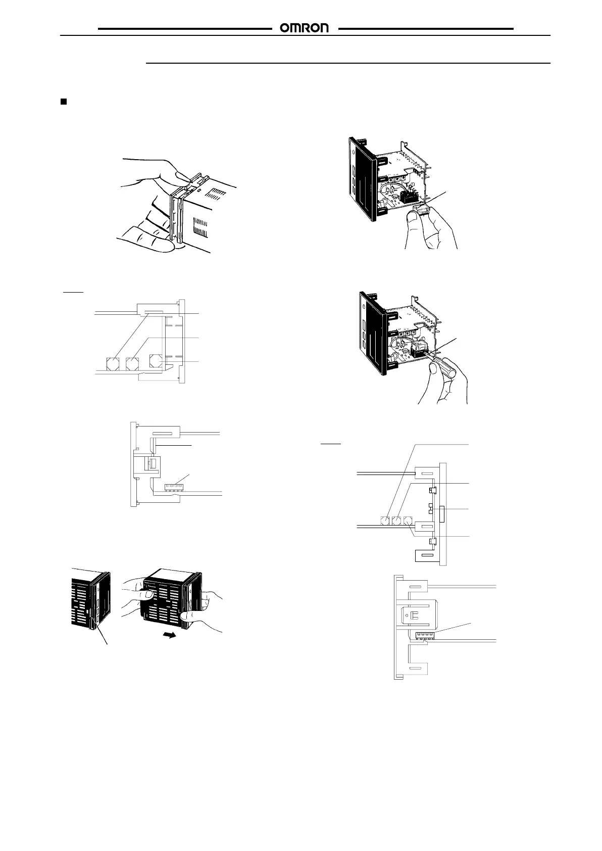
Remove
the internal mechanism from the
housing. Pull out the inter
-
nal mechanism while pressing the hook at the bottom of the front
panel.
Internal Switches
E5CJ
Top
V
iew
Bottom View
Note: A
model with no alarm does not
incorporate
an
alarm mode selector
.
Alarm mode selector 2
(ALM2) (see note)
Alarm mode selector 1
(ALM1) (see note)
Input type selector
(INPUT)
Key protection switch
(PROTECT)
Function selector
(FUNCTION)
E5AJ/E5BJ/E5EJ
1. Remove the internal mechanism from the housing. Pull out
the
internal mechanism while pressing the hook at the bottom
of
the front panel.
Hook
Pull out the internal mechanism
while holding down the hook with
your finger.
When inserting the internal
mechanism back into the case,
push the internal mechanism into
the case until it clicks into place.
2. Connect a Control Output Unit to the vacant socket on the
printed
circuit board as shown below
.
Mount the Control Output Unit
with the mark facing the direc-
tion indicated by the arrow.
Be sure to secure the output
unit with the provided fixture.
To
remove a Control Output Unit, push it up with the tip of a
flat-blade
screwdriver
as shown below
.
Flat-blade
screwdriver
Internal Switches
E5AJ
T
op V
iew
Alarm mode selector 2
(ALM2)
Alarm mode selector 1
(ALM1)
Key protection switch
(PROTECT)
Input type selector
(INPUT)
Function selector
(FUNCTION)
Bottom
V
iew
 Loading...