SYSWAY
SECTION 4 SYSWAY (E5@J and E5@X Format) Communications Procedures
4-8
(1) Header Code
(2) Data Code
Set the data code to “02” only when writing alarm value 2. In all other
cases, set to “01.”
(3) Read Value
For details on the read value ranges, see SECTION 3 Communications
Data for CompoWay/F and SYSWAY.
(4) Precautions
● Alarm Values 1 and 2
When the alarm 1 type is set to “upper and lower-limit alarm,” “upper
and lower-limit range alarm,” or “upper and lower-limit alarm with
standby sequence,” the alarm’s upper and lower limits are set indepen-
dently. The “alarm value 1” setting is disabled and the “alarm value
upper limit 1” and “alarm value lower limit 1” settings are used as the
alarm set values.
For this reason, when “upper/lower-limit alarm” is set, the value of
“alarm value upper limit 1” and not “alarm value 1” is the value read by
communications. The same applies to “alarm 2 type.”
● Temperature Input Shift Value
When the 2-point shift method is used, the “temperature input shift
value” is disabled and the “upper-limit temperature input shift value” and
“lower-limit temperature input shift value” parameters are enabled as
the temperature input shift set values. For this reason, when 2-point
shift method is being used, the “upper-limit temperature input shift
value” is read and not the “temperature input shift values.”
The 2-point shift method will be used in the following cases:
• The “input type” is set to infrared temperature sensor.
• The “input type” is not set to infrared temperature sensor, but the
“input shift type” is set to 2-point shift.
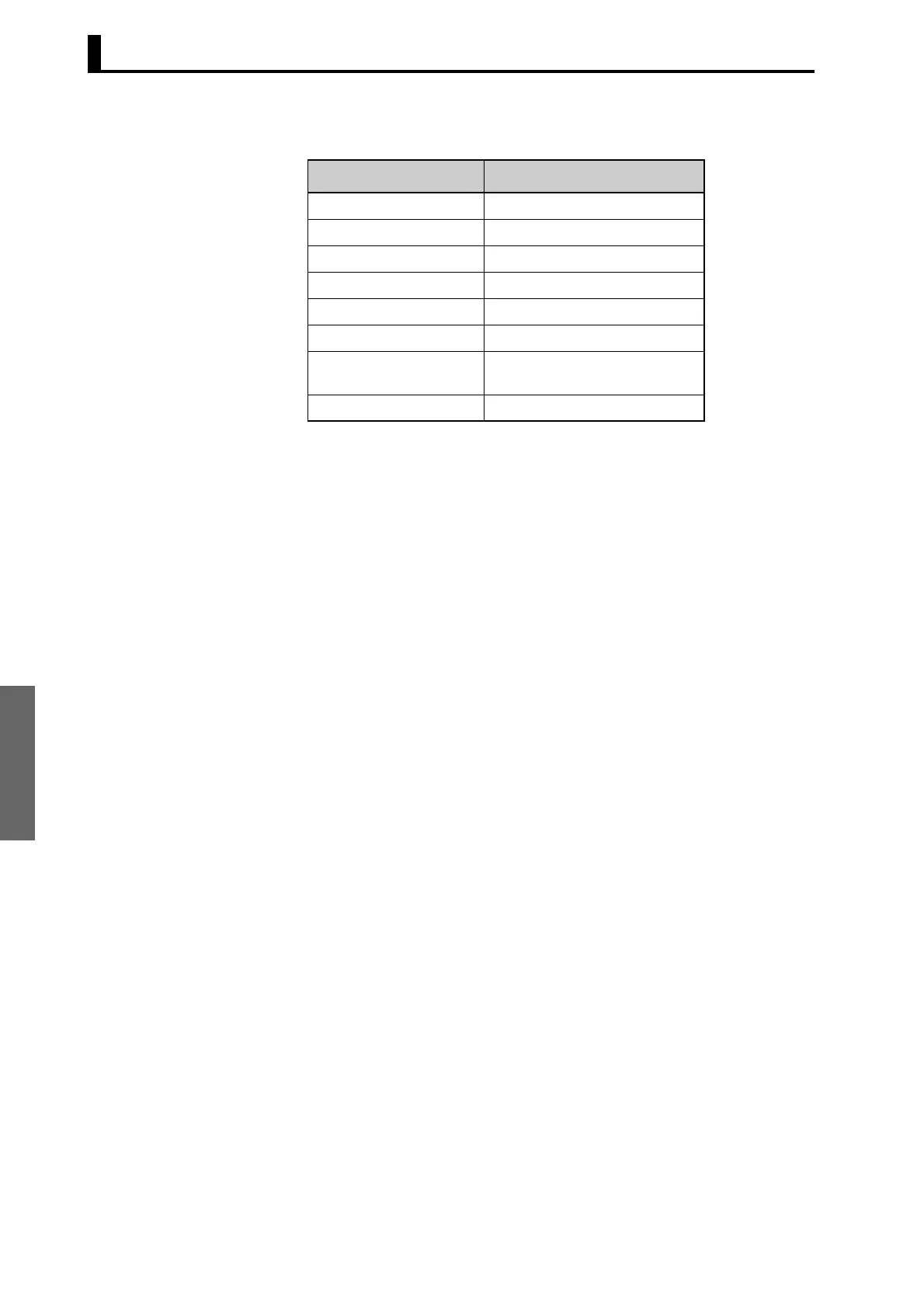
Header code Command
RS Read set point
R% Read alarm value 1/2
RB Read proportional band
RN Read integral time
RV Read derivative time
RI Read input shift values
RW Read temperature heater burn-
out detection
RO Read MV monitor

 Loading...


