SECTION 6 Communications Data for Modbus
6-2
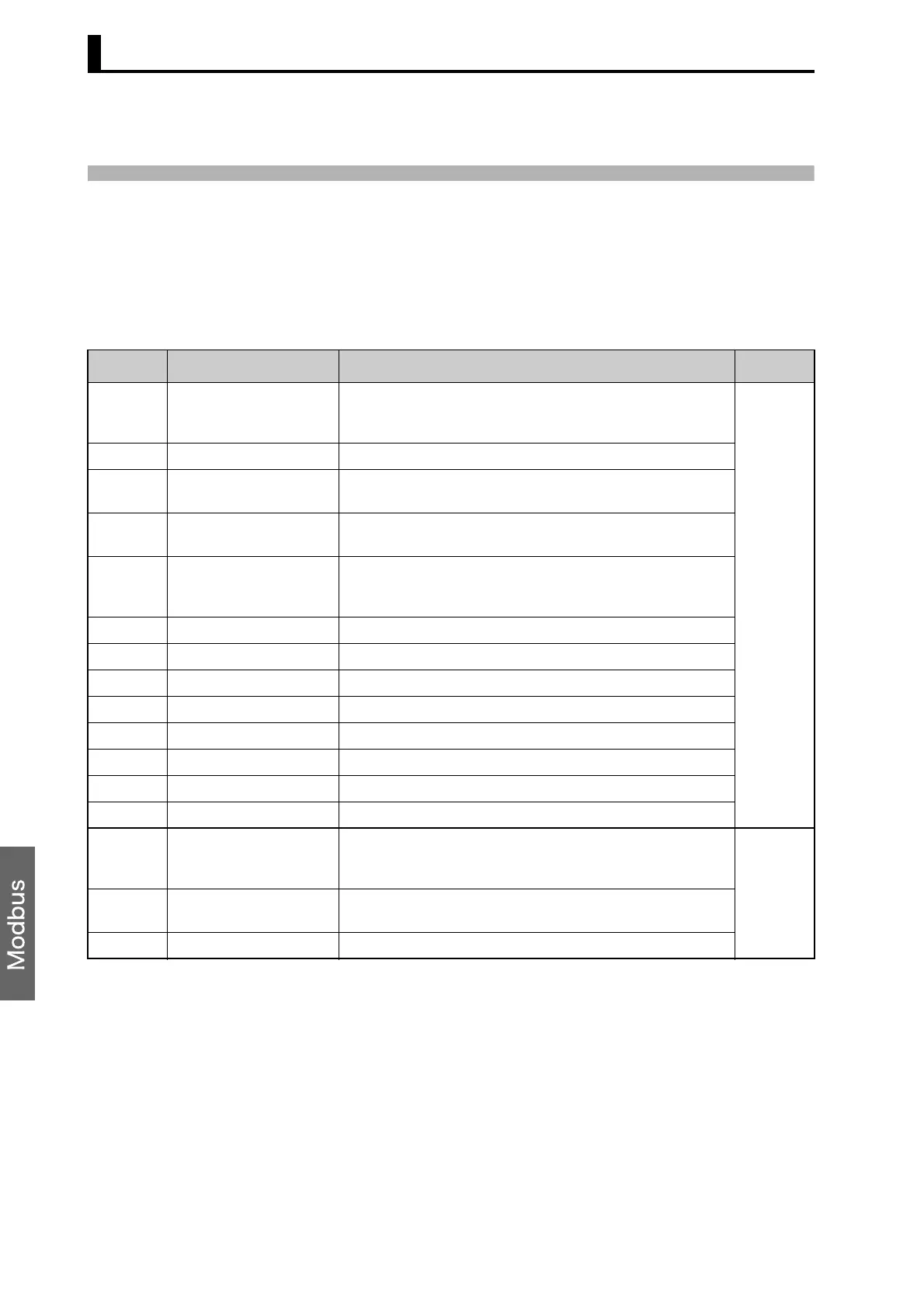
6.1 Variable Area (Setting Range) List
The following table lists the variable areas. Items expressed in
hexadecimal in the “Set (monitor) value” column are the setting range in
the Modbus specifications. Values in parentheses “()” are the actual
setting range.
When there is a section reference for a setting item, refer to that
reference for details.
Address Parameter name Setting (monitor) value Level
0000 PV Temperature: Use the specified range for each sensor.
Analog: Scaling lower limit − 5% FS to Scaling upper limit +
5% FS
Operating
0002 Status (See note 1.) See the Communications Specifications for details.
0004 Internal set point
(See note 1.)
SP lower limit to SP upper limit
0006 Heater current 1 value
monitor
H'00000000 to H'00000226 (0.0 to 55.0)
0008 MV monitor (heating) Standard: H'FFFFFFCE to H'0000041A (−5.0 to 105.0)
Heating and cooling: H'00000000 to H'0000041A (0.0 to
105.0)
000A MV monitor (cooling) H'00000000 to H'0000041A (0.0 to 105.0)
0106 Set point SP lower limit to SP upper limit
0108 Alarm value 1 H'FFFFF831 to H'0000270F (−1999 to 9999)
010A Upper-limit alarm 1 H'FFFFF831 to H'0000270F (−1999 to 9999)
010C Lower-limit alarm 1 H'FFFFF831 to H'0000270F (−1999 to 9999)
010E Alarm value 2 H'FFFFF831 to H'0000270F (−1999 to 9999)
0110 Upper-limit alarm 2 H'FFFFF831 to H'0000270F (−1999 to 9999)
0112 Lower-limit alarm 2 H'FFFFF831 to H'0000270F (−1999 to 9999)
0404 PV Temperature: Use the specified range for each sensor.
Analog: Scaling lower limit − 5% FS to Scaling upper limit +
5% FS
Operating
0406 Internal set point
(See note 1.)
SP lower limit to SP upper limit
040C Status (See note 1.) See the Communications Specifications for details.

 Loading...


