SECTION 5 Modbus Communications Procedure
5-12
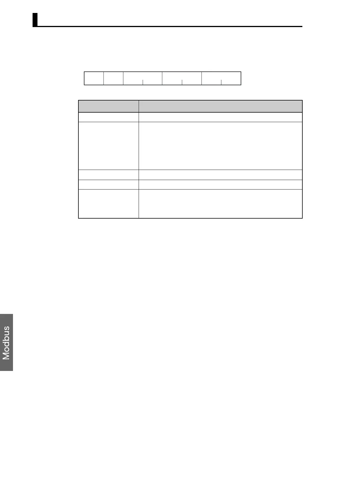
Response Frame
Name Description
Slave address The value from the command frame is entered as-is.
Function code This is the received function code.
When the function ended normally, the function code is left as-is.
When an error occurred, the hexadecimal value of H’80 is added to
the function code to indicate that the response is an error response.
Example: Received function code = H’10
Function code in response frame when an error occurred =
H’90
Write start address This is the received write start address.
Number of elements This is the received number of elements.
CRC-16 This check code is calculated with the data from the slave address to
the end of the data.
For details on the CRC-16 calculation, see CRC-16 Calculation
Example in 5.1 Data Format on page 5-3.
CRC-16
11 2 2
H'10
Number of
Elements
2 bytes
Slave
address
Function
code
Write
start address

 Loading...


