Basic-type Digital Temperature Controller E5CN/E5CN-U 11
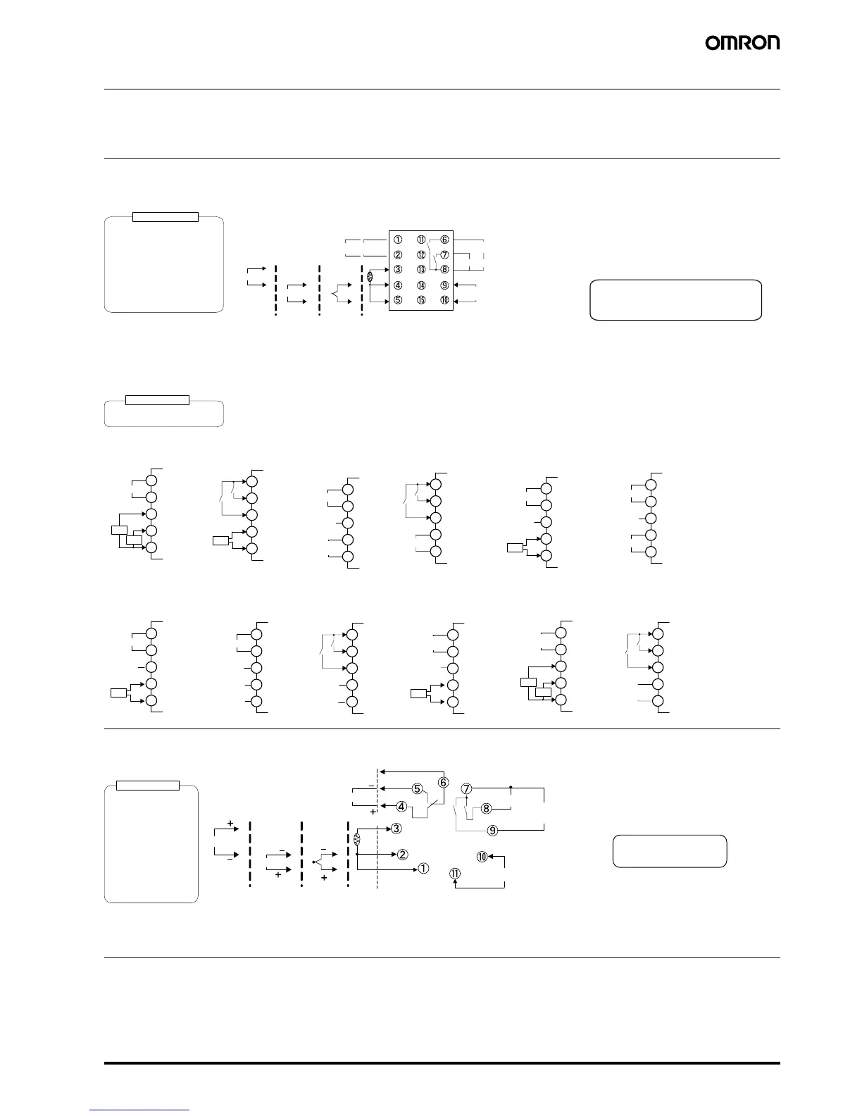
External Connections
• A voltage output (control output, for driving SSR) is not electrically insulated from the internal circuits. When using a grounding thermocouple,
do not connect any of the control output terminals to ground. (If the control output terminals are connected to ground, errors will occur in the
measured temperature values as a result of leakage current.)
• Consult with your OMRON representative before using the external power supply for the ES1B for any other purpose.
E5CN
Controllers
Option Units
E5CN-U
Note: For the Wiring Socket, purchase the P2CF-11 or PG3A-11 separately.
Relay output
250 VAC, 3 A (resistive load)
Voltage output (for driving SSR)
12 VDC, 21 mA
Current output
0 to 20 mA DC
Load: 600 Ω max.
4 to 20 mA DC
Long-life relay output
250 VAC, 3 A (resistive load)
Control output 1
+
−
A
B
B
+
−
Input power supply
Control output 1
Auxiliary outputs (relay outputs)
250 VAC, 3 A
(resistive load)
• 100 to 240 VAC
• 24 VAC/VDC (no polarity)
+
−
+
V
−
Auxiliary output 2
mA
Auxiliary output 1
A heater burnout alarm, heater short alarm,
heater overcurrent alarm, or input alarm is
sent to the output to which the alarm 1
function is assigned.
DO NOT
USE
DO NOT
USE
DO NOT
USE
mA Volt T/c Pt
Analog input Temperature
input
1 1
1 2
1 3
1 4
1 5
E V 1
E V 2
E53-CNHBN2
Event inputs
and CT
1 1
1 2
1 3
1 4
1 5
E53-CNPBN2
Event Inputs and
External Power Supply
E V 1
E V 2
+
−
External
power supply
12 VDC,
20 mA
1 1
1 2
1 3
1 4
1 5
E53-CNPHN2
External Power
Supply and CT
+
−
External
power supply
12 VDC,
20 mA
1 1
1 2
1 3
1 4
1 5
B(+)
A(−)
RS-485
E53-CNP03N2
Communications (RS-485)
and External Power Supply
+
−
External
power supply
12 VDC,
20 mA
1 1
1 2
1 3
1 4
1 5
E53-CNQHN2
Control Output 2
and CT
+
−
Control output 2
1 1
1 2
1 3
1 4
1 5
E V 1
E V 2
E53-CNQBN2
Event Inputs and
Control Output 2
+
−
Control output 2
1 1
1 2
1 3
1 4
1 5
B(+)
A(−)
RS-485
E53-CNHH03N2
Communications
(RS-485) and CT2
1 1
1 2
1 3
1 4
1 5
B(+)
A(−)
RS-485
E53-CNQ03N2
Communications
(RS-485) and
Control Output 2
+
−
Control output 2
1 1
1 2
1 3
1 4
1 5
B(+)
A(−)
RS-485
E53-CN03N2
Communications
(RS-485)
1 1
1 2
1 3
1 4
1 5
E V 1
E V 2
E53-CNBN2
Event inputs
1 1
1 2
1 3
1 4
1 5
E53-CNQHHN2
Control Output 2
and CT2
+
−
Control output 2
1 1
1 2
1 3
1 4
1 5
B(+)
A(−)
RS-485
E53-CNH03N2
Communications
(RS-485) and CT
DO NOT
USE
DO NOT
USE
DO NOT
USE
DO NOT
USE
DO NOT
USE
DO NOT
USE
DO NOT
USE
DO NOT
USE
DO NOT
USE
DO NOT
USE
CT1
CT1
CT1
CT1
CT1
CT1
CT2
CT2
Voltage output (for driving SSR)
12 VDC, 21 mA
Control output 2
A
B
B
Auxiliary output
250 VAC, 3 A (resistive load)
Control output 1
Input power supply
• 100 to 240 VAC
• 24 VAC/VDC (no polarity)
Auxiliary output 1
(Relay outputs)
V
m A
An input error is sent to the
output to which the alarm 1
function is assigned.
Current output
0 to 20 mA DC
Relay output
(three terminals used)
SPDT, 250 VAC, 3 A
(resistive load)
Voltage output
(for driving SSR)
12 VDC, 21 mA
Load: 600 W max.
4 to 20 mA DC
Control output 1
Auxiliary output 2
(Control output (cooling side))
DO NOT
USE
DO NOT
USE
DO NOT
USE
mA Volt T/c Pt
Analog input Temperature
input

 Loading...


