16 Basic-type Digital Temperature Controller E5CN/E5CN-U
M
M
M
M
M
M
M
psel
cwf
u-no
1
bps
9.6
len
7
sbit
2
prty
even
sdwt
20
Starting in manual mode.
M
M
M
M
M
M
pmov
0
oapt
0
pmsk
on
prlp
0
icpt
1
wtpt
off
25
M
M
M
M
M
M
M
M
M
M
ST (Self-tuning)
M
M
M
M
in-t
5
in-h
100
in-l
dp
d-u
sl-h
1300
sl-l
-200
cntl
onof
s-hc
stnd
st
on
ptrn
off
cp
20
c-cp
20
orev
or-r
0
0
c
M
M
M
l.adj
cmwt
off
at
off
M
M
M
M
M
M
ct1
0.0
0.0
0.0
hb1
0.0
hb2
0. 0
M
M
50.0
50.0
M
M
oc1
50.0
oc2
50.0
M
M
M
sp-0
0
sp-1
0
sp-2
0
sp-3
0
M
M
M
M
M
M
M
M
M
M
M
M
M
M
M
M
of-r
50.0
soak
1
c-sc
1.00
d
40
p
8.0
i
233
c-db
0.0
hys
1.0
chys
1.0
ol-l
-5.0
wt-b
off
mv-s
0.0
mv-e
0.0
ol-h
105.0
M
M
M
ins
0.0
insh
0.0
insl
0. 0
sprt
off
sqrp
0.0
M
M
M
a-m
25
25
0
M
M
M
M
M
M
M
sp-m
0
ct1
0.0
ct2
0.0
lcr1
0.0
lcr2
0.0
prst
rset
sktr
0
M
m-sp
0
r-s
run
M
M
M
M
M
M
M
M
M
M
M
M
c-o
0.0
al-1
0
al1h
0
al1l
0
al- 2
0
al2h
0
al2l
0
al-3
0
al3l
0
al3h
0
o
0.0
M
orl
0.0
M
ct2
lcr1
hs1
lcr2
hs2
0.0
0.0
alh1
0.2
M
alt1
2
M
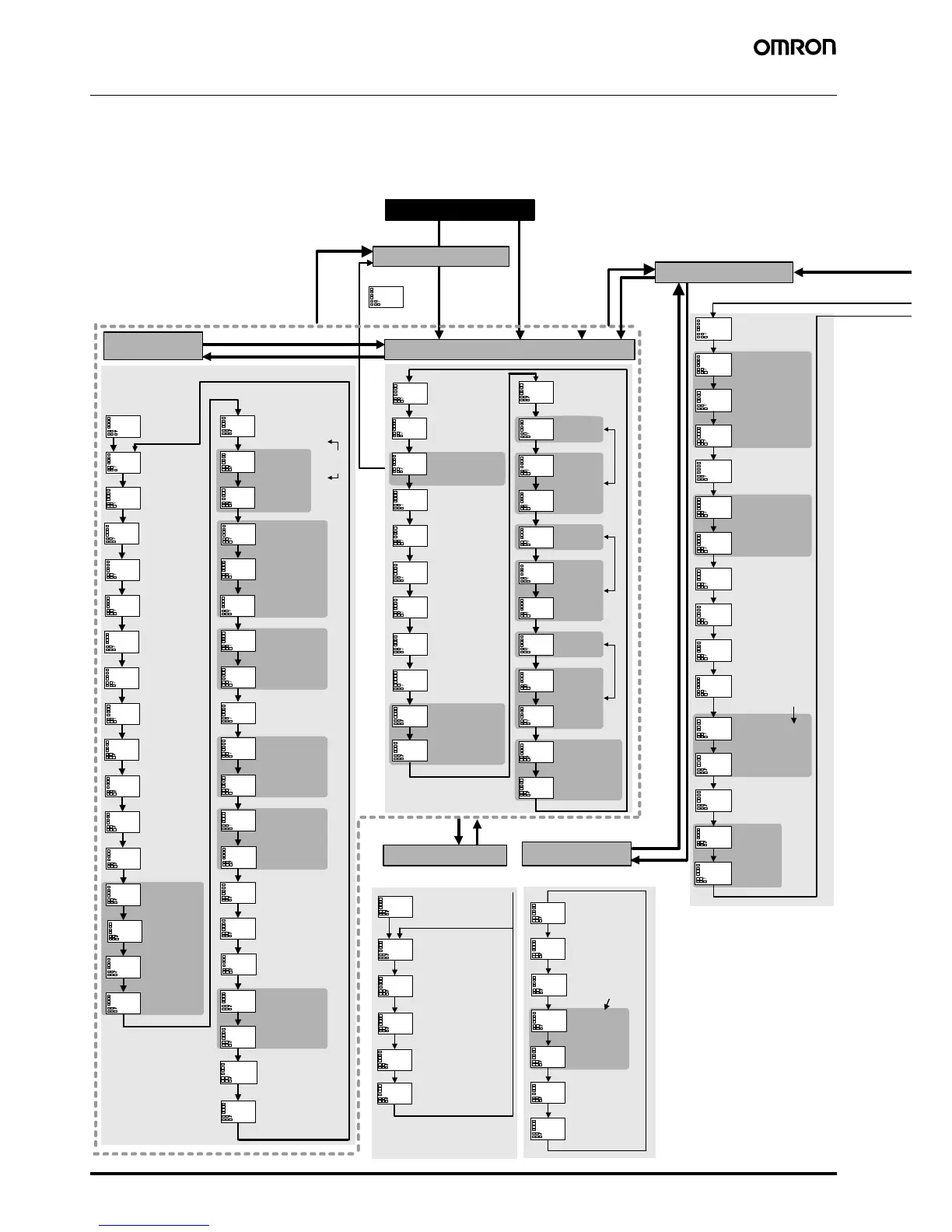
Power ON
Starting in
automatic
mode.
Manual Control Level
PID
Control
only
PV/MV
Press the O Key less than 1 s.
Press the O Key less than 1 s.
Operation Level
Adjustment
Level
Adjustment Level
Display
Displayed only
once when
entering
adjustment level.
AT Ex e c ute/Cancel
Communications
Writing
Heater Current 1
Value Monitor
Heater Burnout
Detection 1
Heater Overcurrent
Detection 1
Heater Current 2
Value Monitor
Heater Burnout
Detection 2
Heater Overcurrent
Detection 2
Leakage Current 1
Monitor
Leakage Current 2
Monitor
HS Alarm 1
HS Alarm 2
C
SP 0
SP 1
C
C
SP 2
SP used by
multi-SP
SP 3
C
C
C
C
C
C
C
C
Temperature Input Shift
1-point shift
2-point shift
Set either
of these
parameters.
Upper Limit
Temperature
Input Shift Value
Lower Limit
Temperature
Input Shift Value
Proportional Band
Integral Time
PID settings
Derivative Time
Cooling Coefficient
Heating/cooling
Dead Band
Manual Reset Value
Clear the offset during
stabilization of P or PD
control.
Hysteresis (Heating)
Hysteresis (Cooling)
Hysteresi
s settings
C
Soak Time
Wait Band
MV at Stop
MV at PV Error
C
SP Ramp Set Value
MV Upper Limit
MV Lower Limit
MV Change Rate Limit
Extraction of Square Root
Low-cut Point
C
Process Value
Added when Additional
PV display is ON.
C
Process Value/
Set Point
C
C
C
Auto/Manual Switch
PID control only.
Added when
auto/manual select
addition is ON.
Multi-SP
Set Point Setting
Set Point During
SP Ramp
Heater Current 1 Value
Monitor
Heater Current 2 Value
Monitor
Leakage Current 1
Monitor
Leakage Current 2
Monitor
Program Start
Soak Time Remain
Press the O and M Keys for
a
t least 3 s.
Protect Level
Press the O and M Keys for at least 1 s.
Press the O Key
less than 1 s.
Communications
Setting Level
Note: The time taken to move to the protect
level can be adjusted by changing the
"Move to protect level time" setting.
Note: Displayed only for models with communications.
Changes are effective after cycling power or
after a software reset.
Move to Protect Level:
Displayed only when a password
is set. Restricts moving to protect
level.
Operation/Adjustment Protect:
Restricts displaying and
modifying menus in operation,
adjustment, and ma
nual control
levels.
Initial Setting/
Communications Protect:
This protect level restricts movement
to the initial setting, communications
setting, and advanced function setting
levels.
Setting Change Protect:
Protects changes to setups by
operating the front panel keys.
Password to Move to Protect Level:
Password setting
Parameter Mask Enable:
Displayed only when a
parameter mask is set.
Protocol Setting:
Switches between
CompoWay/F (SYSWAY)
and Modbus.
Communications Unit No.
Communications
Baud Rate
CompoWay/F
(SYSWAY) only
Communications
Data Length
Communications
Stop Bits
Communica
tions Parity
Send Data Wait Time
C
RUN/STOP
Alarm Value 1
Set either of these parameters.
Alarm Value
Upper Limit 1
Alarm Value
Lower Limit 1
C
C
C
C
Alarm Value 2
Set either of these parameters.
Alarm Value
Upper Limit 2
Alarm Value
Lower Limit 2
Alarm Value 3
C
C
C
Alarm Value
Upper Limit 3
Alarm Value
Lower Limit 3
Set either of these parameters.
MV Monitor (Heating)
MV Monitor (Cooling)
Press the
O Key for
at least 1 s.
Press the O Key less than 1 s.
Initial Setting Level
Input Type
Scaling Upper Limit
Scaling Lower Limit
Decimal Point
For input type of analog
C
C
Temperature Unit
°C, °F
For input type of
temperature
SP Upper Limit
SP Lower Limit
Limit the set point
PID ON/OFF
Standard or
Heating/Cooling
For input type of
temperature, standard
control, or PID
Program Pattern
When assigning PID or
control output to ON/OFF
output
Control Period (Heating)
Control Period (Cooling)
Set the ON/OFF
output cycle.
Direct/Reverse Operation
C
Alarm 1 Type
Alarm 1
Hysteresis
Press the O Key for at least 3 s.
Other than the Auto/Manual Switch display
Press the
O Key for at
least 1 s.
Press the
O Key
for at
least 3 s.
Parameters
Basic Type
Some parameters are not displayed depending on
the model of the Controller and parameter settings.
For details, refer to the E5CN/E5AN/E5EN Digital
Temperature Controllers User's Manual Basic Type
(Cat. No. H156).

 Loading...


