Solid-state Multi-functional Timer H3CR-A 13
Operation
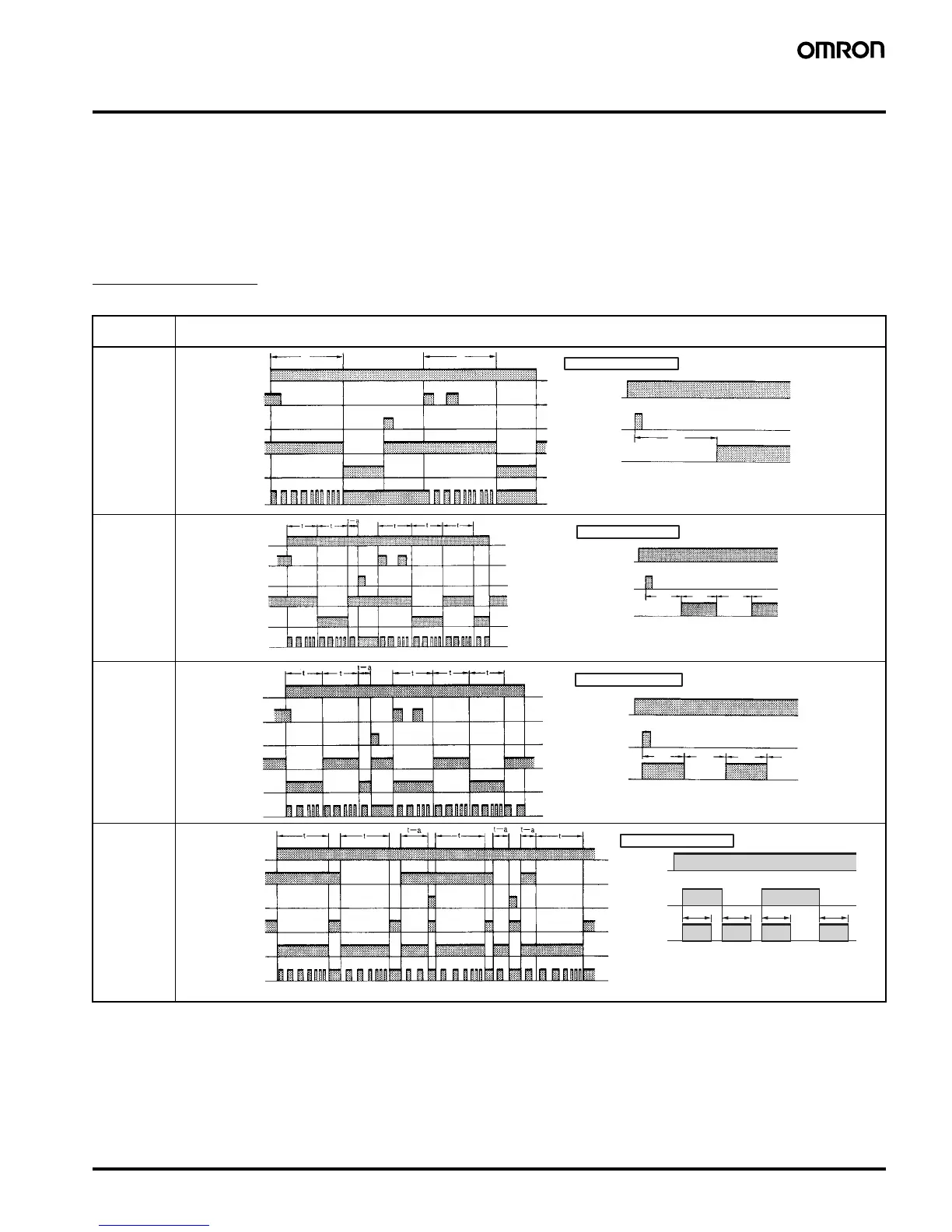
■ Timing Chart
Note: 1. The minimum power-opening time (“Rt”) is 0.1 s.
2. The minimum input pulse width (for start, reset) is 0.05 s.
3. The letter “t” in the timing charts stands for the set time and “t–a” means that the period is less than the time set.
4. Power supply start in mode J is also possible for H3CR-A8/-A8E/-A8S/-A8-301 models.
5. Refer to page 19 for application examples.
H3CR-A/-AS/-AP*
*H3CR-AP model incorporates start input only.
Operating
mode
Timing chart
A: ON-delay
B:
Flicker OFF
start
B2:
Flicker ON
start
C:
Signal ON/
OFF-
delay
t t
t
Power
Start
Reset
Output relay (NC)
Power indicator
Power
Output
Basic operation
Output relay (NO)
(Output indicator)
Start
(See note)
Note: Start input is invalid while the
Timer is in operation.
t t t t
Basic operation
Power
Output
Power
Power indicator
Start
Reset
Output relay (NC)
Output relay (NO)
(Output indicator)
Start
(See note)
Note: Start input is invalid while
the Timer is in operation.
t
t
t t
Basic operation
Power
Output
Power
Start
Reset
Power indicator
Output relay (NC)
Output relay (NO)
(Output indicator)
Start
(See note)
Note: Start input is invalid while the
Timer is in operation.
tttt
Basic operation
Power
Output
Power
Start
Reset
Output relay (NC)
Power indicator
Output relay (NO)
(Output indicator)
Start
(See note)
Note: Start input is valid and re-
triggerable while the Timer is
in operation.
 Loading...