H3DEH3DE
Operation
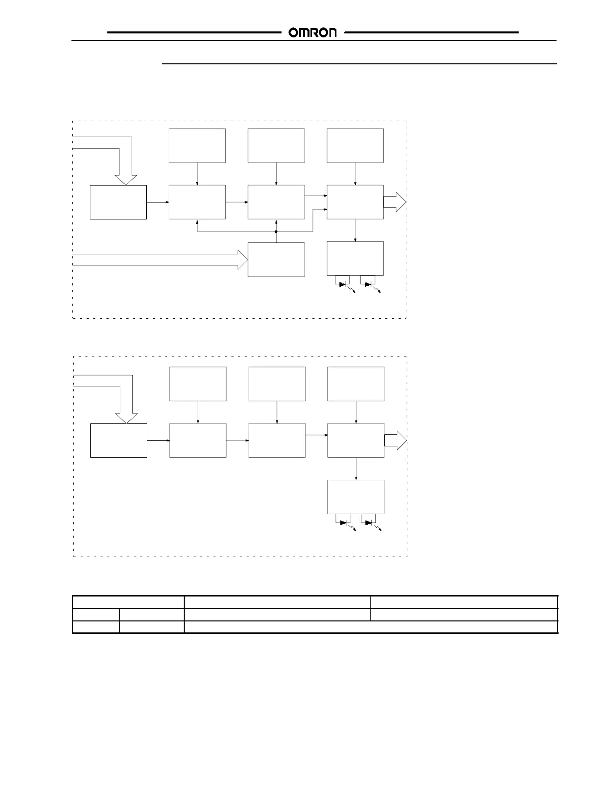
J BLOCK DIAGRAM
H3DE-M1/-M2
AC (DC) input
Power supply
circuit
Zero setting
detection
circuit
Oscillation
circuit
Time range/
unit selectors
Counting
circuit
Operating
mode selector
Output circuit
Indicator
circuit
Power-ON
indicator
Output
indicator
Start input
Input circuit
AC (DC) input
Power supply
circuit
Zero setting
detection
circuit
Oscillation
circuit
Time range/
unit selectors
Counting
circuit
Operating
mode selector
Output circuit
Indicator
circuit
Power-ON
indicator
Output
indicator
H3DE-S1/-S2
J I/O FUNCTIONS
Item H3DE-M1/-M2 H3DE-S1/-S2
Input Start Starts operation. No input is available.
Output Control output Outputs are turned ON according to designated output mode when preset value is reached. (See Note.)
Note: When the output type selector switch on the bottom of the Timer is set to the instantaneous side, the relay R2 (terminal numbers
21/25, 22/26, and 24/28) becomes an instantaneous contact and turns ON/OFF in synchronization with the changes in the power
supply.
 Loading...