H3DR-F/G/H
H3DR-F/G/H
108
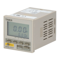
Mounting and Dismounting
The H3DR should be mounted as horizontally as possible.
Whenmountingthe H3DR on asocket mountingtrack, hookportion
(A) of the Timer to an edge of the track first, and then depress the
Timer in the direction of (B).
(A)
(B)
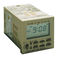
When dismounting the H3DR, pull out portion (C) with a flat-blade
screwdriver and remove the Timer from the mounting track.
30 mm max.
The H3DR can be mounted and dismounted with ease if a distance
of 30 mm or more is kept between the H3DR and other equipment.
Environment
WhenusingtheTimerinanarea withexcess electronic noise,sepa-
rate the Timer and wiring as far as possible from the noise sources.
Organic solvents (such as paint thinner), as well as very acidic or
basic solutions can damage the outer casing of the Timer.
Others
If the Timer is mounted on a control board, dismount the timer from
the control board orshort-circuit the circuitry of the power board be-
fore carrying out a voltage withstand test between the electric cir-
cuitry and non current-carrying metal part of the Timer, in order to
prevent the internal circuitry of the Timer from damage.
Changing Switches
Thetimeunit andtimerange canbesetbyturningthemeitherclock-
wise or counterclockwise.
The switches are designed to click into place. Be sure that the
switchesareintheproperplaceanddonot leavethem betweenset-
tings. Leaving switches between settings can cause faulty opera-
tion.
Wiring (H3DR-H)
The H3DR has a high impedance circuit. Therefore, the H3DR may
not be reset if the H3DR is influenced by inductive voltage. In order
to eliminate any influence of inductive voltage, the wires connected
to the H3DR must be as short as possible and should not be
installed alongside power lines. If the H3DR is influenced by induc-
tive voltage that is 30% or more of the rated voltage, connect a CR
filter with a capacitance of approximately 0.1
&
F and a resistanceof
approximately 120
$
or a bleeder resistor between the power sup-
ply terminals. If there is any residual voltage dueto current leakage,
connect a bleeder resistor between the power supply terminals.
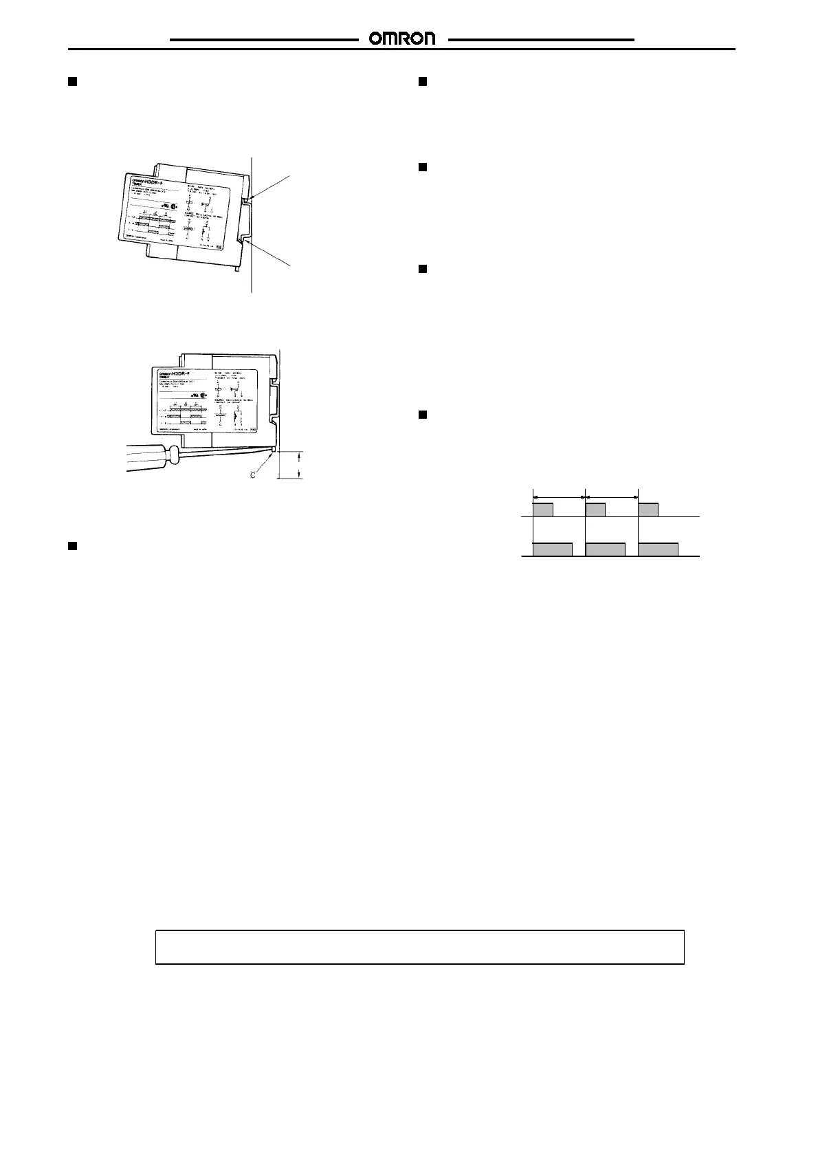
Operation (H3DR-H)
An interval of 3 s minimum is required to turn on the H3DR after the
H3DR is turned off. If the H3DR is turned on and off repeatedly with
an interval of shorter than 3 s, the internal parts of the H3DR may
deteriorate and the H3DR may malfunction.
Power
Output state
3smin.
ALL DIMENSIONS SHOWN ARE IN MILLIMETERS.
To convert millimeters into inches, multiply by 0.03937. To convert grams into ounces, multiply by 0.03527.
Cat. No. L87-E1-1A
 Loading...