STP
STP
229
Installation
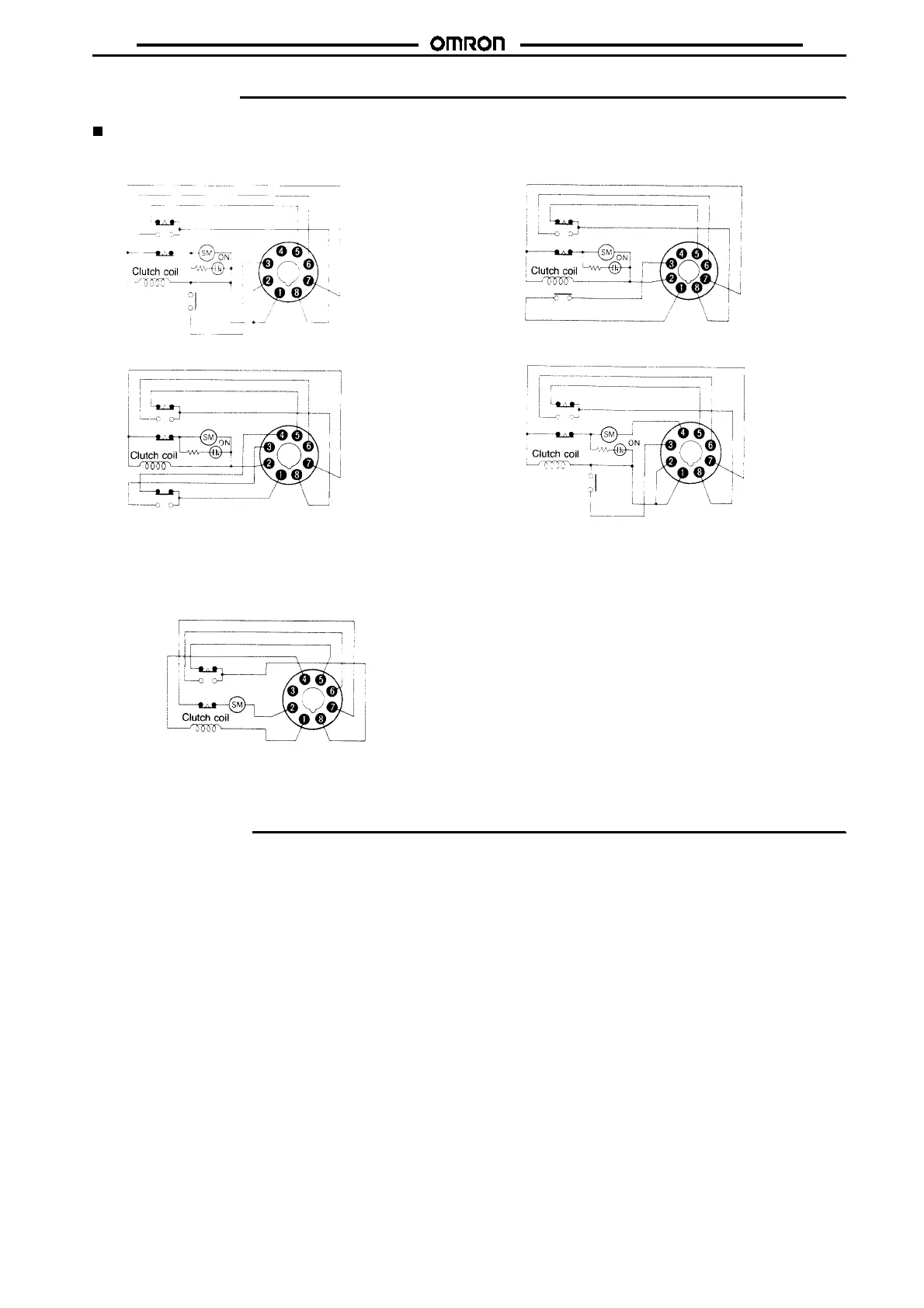
Terminal Arrangement
STP-N/STP-NM
STP-Y/STP-YM
STP-NH
STP-ND STP-N2
STP-NR
Note: Connect the motor drive power source between terminals
D
and
G
and the clutch operating power
source between terminals
B
and
G
. In this case, be sure that both power sources are one and the
same and the power source to be connected to terminal
G
is of the same phase.
Note: The Electrical Presetting type is not
providedwithanoperationindicator.
Precautions
Connection
Connecting the Power Supply
Power supply is connected separately for the motor and the clutch.
Connect the motordrive power supply across terminals 4and 7and
connecttheclutchoperationpowersupplyacross terminals2and7.
Power supplied for both of these must be from the same power
source and the same phase must be connected to terminal 7. For
STP-Rmodels,usedthevoltageappliedfortheclutchpowersupply
for resetting. Do not apply power continuously for both the motor
and clutch power supplies for extended periods of time.
Connecting Instantaneous Contact Circuit
Socket terminals 1 and 3 are for an instantaneous contact circuit
and are normally open. Terminal 1 is internally connected to termi-
nal 2 to connect power. The same phase must be used for both ter-
minal2andforterminals 1and 3. The controlledloadmusttherefore
be connected to the same phase of power as thepower supply con-
nected across terminals 3 and 7. The instantaneous contact circuit
for terminals 1 and3 can beused as a self-holding circuit for thetim-
er. This circuit, however, is electrically independent of the operation
power circuits for STP-NH and STP-ND.
Setting the Operating Time
Do not turn the adjustment for the operating time past the range on
the scale. If the clutchdoes notrelease then current is appliedtothe
clutch coil when using a power reset, the moving needle will not
move with the setting needle when the set time is increased (i.e.,
when the setting needle is turned clockwise).
 Loading...