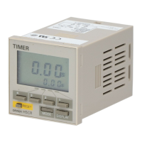
4 Multifunction Digital Timer H5CX-A/-L
Specifications
■ Ratings
Note 1. Inrush current will flow for a short time when the power supply is turned ON. Refer to Inrush Current (Reference Values) on page 6.
2. The display is lit only when the power is ON.
Item H5CX-A@ H5CX-A11@ H5CX-L8@
Classification Digital timer
Rated supply voltage 100 to 240 VAC (50/60 Hz), 24 VAC (50/60 Hz)/12 to 24 VDC (permissible ripple: 20% (p-p) max.)
Operating voltage range 85% to 110% rated supply voltage (12 to 24 VDC: 90% to 110%)
Power consumption
(See note 1.)
Approx. 6.2 VA at 264 VAC
Approx. 5.1 VA at 26.4 VAC
Approx. 2.4 W at 12 VDC
Mounting method Flush mounting Flush mounting, surface mounting, DIN track mounting
External connections Screw terminals 11-pin socket 8-pin socket
Terminal screw tightening
torque
0.5 N·m max. ---
Display
(See note 2.)
7-segment, negative transmissive LCD;
Present value:
11.5-mm-high characters,
red or green (programmable)
Set value: 6-mm-high characters, green
7-segment, negative transmissive LCD
Present value:
11.5-mm-high characters, red
Set value: 6-mm-high characters, green
Digits 4 digits
Time ranges 9.999 s (0.001-s unit), 99.99 s (0.01-s unit), 999.9 s (0.1-s unit), 9999 s (1-s unit), 99 min 59 s (1-s unit)
999.9 min (0.1-min unit), 9999 min (1-min unit), 99 h 59 min (1-min unit), 999.9 h (0.1-h unit), 9999 h (1-h unit)
Timer mode Elapsed time (Up), remaining time (Down) (selectable)
Input signals Signal, reset, gate Signal, reset
Input method No-voltage input/voltage input (switchable)
No-voltage Input
ON impedance: 1 kW max. (Leakage current: 5 to 20 mA when 0 W)
ON residual voltage: 3 V max.
OFF impedance: 100 k
W min.
Voltage Input
High (logic) level: 4.5 to 30 VDC
Low (logic) level: 0 to 2 VDC
(Input resistance: approx. 4.7 k
W)
No-voltage Input
ON impedance: 1 kW max. (Leak-
age current: 5 to 20 mA when 0
W)
ON residual voltage: 3 V max.
OFF impedance: 100 k
W min.
Signal, reset, gate Minimum input signal width: 1 or 20 ms (selectable, same for all input)
Reset system Power resets (except for A-3, b-1, and F modes), external and manual reset
Power reset Minimum power-opening time: 0.5 s (except for A-3, b-1, and F mode)
Reset voltage 10% max. of rated supply voltage
Sensor waiting time 250 ms max. (Control output is turned OFF and no input is accepted during sensor waiting time.)
Output modes A, A-1, A-2, A-3, b, b-1, d, E, F, Z, ton or toff
One-shot output time 0.01 to 99.99 s
Control output SPDT contact output: 5 A at 250 VAC/30 VDC, resistive load (cos
f=1)
Minimum applied load: 10 mA at 5 VDC (failure level: P, reference value)
Transistor output: NPN open collector, 100 mA at 30 VDC max.
residual voltage: 1.5 VDC max. (Approx. 1 V)
Leakage current: 0.1 mA max.
Output category according to EN60947-5-1 for Timers with Contact Outputs (AC-15; 250 V 3 A/AC-13; 250 V 5 A/
DC-13; 30 V 0.5 A)
Output category according to EN60947-5-2 for Timers with Transistor Outputs (DC-13; 30 V 100 mA)
NEMA B300 Pilot Duty, 1/4 HP 5-A resistive load at 120 VAC, 1/3 HP 5-A resistive load at 240 VAC
Key protection Yes
Memory backup EEPROM (overwrites: 100,000 times min.) that can store data for 10 years min.
Ambient temperature Operating:
-10 to 55°C (-10 to 50°C if timers are mounted side by side) (with no icing or condensation)
Storage:
-25 to 65°C (with no icing or condensation)
Ambient humidity 25% to 85%
Case color Black (N1.5)
Attachments Waterproof packing,
flush mounting adapter,
label for DIP switch settings
Label for DIP switch settings None
 Loading...