H7CL
H7CL
3
Characteristics
Item H7CL-Aj
(AC models)
H7CL-ADj
(DC models)
Insulation resistance
100 M
Ω
min. (at 500 VDC) (between current-carrying terminal and exposed non-current-carrying metal
parts, and between non-continuous contacts)
Dielectric strength
2,000 V
AC, 50/60 Hz for 1 min
(between current-carrying terminal and exposed
non-current-carrying metal parts)
1,000 V
AC, 50/60 Hz for 1 min
(between non-continuous contacts)
2,000 V
AC
(AD: between current-carrying terminal and
exposed non-current-carrying metal parts)
1,000 V
AC
(ADS: between current-carrying terminal and
exposed non-current-carrying metal parts)
1,000 V
AC
(between non-continuous contacts)
Impulse withstand voltage
3 kV (between power terminals)
4.5 kV (between current-carrying terminal and
exposed non-current-carrying metal parts)
1 kV (between power terminals)
1.5 kV (between current-carrying terminal and
exposed non-current-carrying metal parts)
Noise immunity
±
1.5 kV (between power terminals)
±
600 V (between input terminals), square-wave
noise by noise simulator (pulse width: 100 ns/1
µs, 1-ns rise)
±
480 V (between power terminals)
±
600 V (between input terminals), square-wave
noise by noise simulator (pulse width: 100 ns/1
µs, 1-ns rise)
Static immunity
Malfunction: 8 kV
Destruction: 15 kV
V
ibration resistance
Destruction:
10 to 55 Hz, 0.75-mm single amplitude each in three directions
Malfunction:
10 to 55 Hz, 0.5-mm single amplitude each in three directions
Shock resistance
Destruction:
294 m/s
2
(30G) each in three directions
Malfunction:
98 m/s
2
(10G) each in three directions
Ambient temperature
Operating: –10°
C to 55
°
C (–10
°
to 50
°
C if Counters are mounted side by side) (with no icing)
Storage: –25°
C to 65
°
C (with no icing)
Ambient humidity
Operating: 35% to 85%
EMC (EMI): EN50081-2
Emission Enclosure: EN55011 Group 1 class A
Emission AC Mains:
EN55011 Group 1 class A
(EMS): EN50082-2
Immunity ESD:
EN61000-4-2:
4 kV contact discharge
8 kV air discharge
Immunity RF-interference:
ENV50140:
10 V/m (Amplitude-modulated, 80 MHz to 1 GHz)
10 V/m (Pulse-modulated, 900 MHz)
Immunity Conducted Disturbance:
ENV50141:
10 V (0.15 to 80 MHz)
Immunity Burst:
EN61000-4-4:
2 kV power-line
2 kV I/O signal-line
Life expectancy
Mechanical:
10 million operations min.
Electrical:
100,000 operations min. (3 A at 250 V
AC, resistive load)
Weight
Approx. 130 g
Approx. 1
10 g
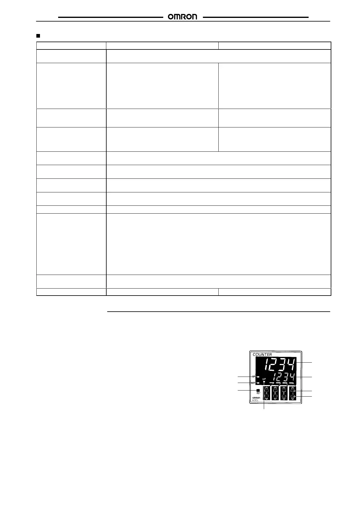
Nomenclature
Indicator
1.
Present V
alue
Red LEDs with a character height of 12 mm; leading zeros
suppressed
2. Set
V
alue
Green LEDs with a character height of 8 mm; leading zeros
suppressed
3. Reset
Indicator
4.
Key Protection Indicator
5. Control Output Indicator
Operation Key
6. Reset (RST) Key
The RST Key initializes the present value and control output.
7.
Increment Keys (1 to 4)
Up Keys 1 to 4 increment the set value.
8.
Decrement Keys (1 to 4)
Down Keys 1 to 4 decrement the set value.
1
2
3
4
5
6
7
8