H7CL
H7CL
8
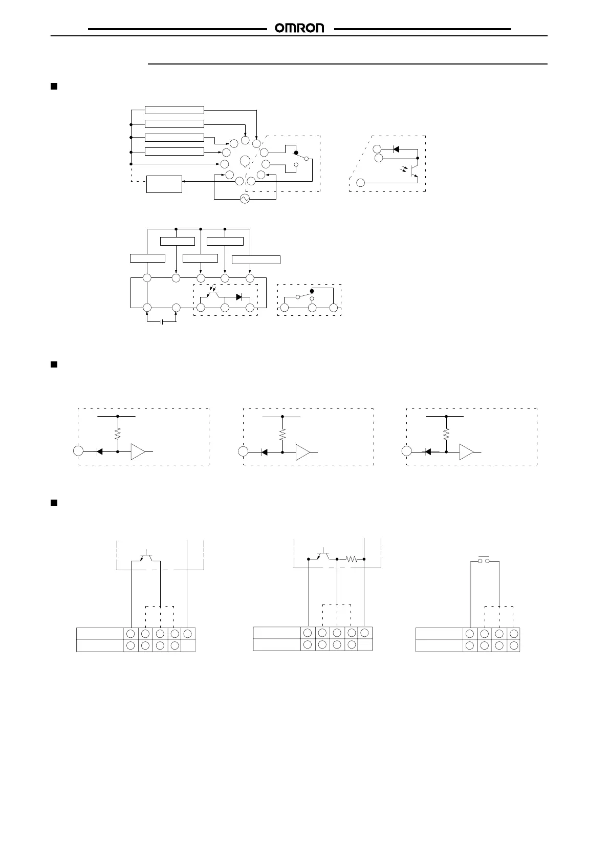
Installation
Terminal Arrangement
AC
Models
DC Models
Note:
1 and 6 are connected to each other internally
.
8109
7
54
3
2 54
3
Gate
Key protection
0 V
Reset Count
12 to 24 VDC
Contact outputTransistor output
6
7
8
9
10
5
4
3
2
Reset
Count
Gate
Key protection
External power supply
12 VDC (50 mA max.)
11
1
8
9
11
Transistor output
Contact output
100 to 240VAC
Input common (0 V)
6
1
–+
Load
(Sensor)
(–) (+)
Note: Power
supply circuit is insulated from the internal
circuit
(or I/O).
Input Circuitry
Count,
Reset, and Gate Input
H7CL-Aj
(AC Models)
Key
Protection Input
IN
V
in
– 3.5V
(16V max.)
1 kΩ
Internal circuitry
V
in
: Supply voltage
H7CL-ADj
(DC Models)
IN
+12 V
1 kΩ
Internal circuitry
IN
Internal circuitry
+5 V
4.7 kΩ
Note: No key input is effective while
key protection input is ON.
Input Connections
Open Collector Output
Contact input
Voltage Output
12 VDC
17653
–
7986
PLC or sensor
0 V Output
12 VDC
PLC or sensor
0 V Output
7653
7986
AC models
DC models
17653
–
7986
AC models
DC models
AC models
DC models
Gate input
Count input
Reset input
12 VDC output
Gate input
Count input
Reset input
12 VDC output
Gate input
Count input
Reset input
0 V
0 V
Count,
Reset, and Gate Input Specification
ON impedance:
500Ω
max. (the leakage current is 5 to 20 mA when the impedance is 0
Ω.)
ON residual voltage: 2 V max.
OFF impedance:
100kΩ
min.
Maximum applied voltage:
30 VDC max.
 Loading...


