H8BM
H8BM
2
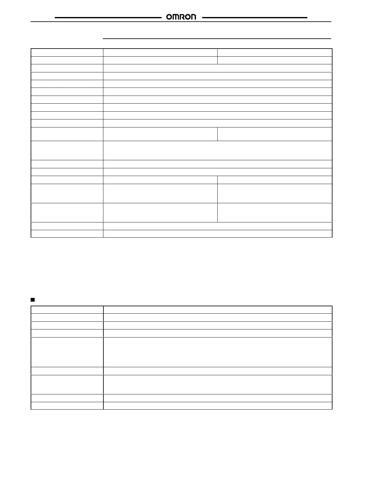
Specifications
Item H8BM-B, H8BM-BP H8BM-BD, H8BM-BDP
Classification
3-stage setting 1-stage setting
Mounting method
Flush mounting
External connections
Screw terminals
Enclosure ratings
IP54F (panel surface)
Display mode
Up display
Output mode
F mode
Reset system
External, manual resets
T
iming function
Yes
Input signal method
V
oltage inputs: High and low signal voltages (count, reset, re-monitor
, counter select, I/O inhibit)
Control output No-contact outputs: NPN outputs (RUN, forecast,
machine stoppage) (PNP outputs for -BP)
No-contact outputs: NPN outputs (RUN, forecast)
(PNP outputs for -BDP)
Display
Count, preset value, counter number
, and error codes displayed on 7-segment LCD Power-ON, mode,
reset, I/O inhibit, and re-monitor modes displayed on LCD characters
Output indication on LCD characters and LEDs
LCD with backlight Yes
Built-in counter number
9 (counters 1 to 9) (see Note 1)
Number of stages
3 stages (see Note 2)
1 stage (see Note 5)
Digits
Forecast value:
6 digits (999999)
Pre-forecast value:
–5 digits (see Note 3)
Machine stoppage:
+5 digits (see Note 4)
6 digits (999999)
Max. time settings
Forecast value:
99999.9 hr (0.1 hr or more)
Pre-forecast value:
–9999.9 hr (see Note 3)
Machine stoppage:
+9999.9 hr (see Note 4)
99999.9 hr (0.1 hr or more)
Memory backup
Backup time for power interruption: Approx. 10 years at 25
°C
Approved standards
UL508, CSA C22.2 No.14
Note: 1.
Each channel operates on an separate I/O.
2. Pre-forecast:
Displayed only on LCD (No external output is provided.)
Forecast:
Displayed on LCD and LED and output (Output for each Counter)
Machine stoppage:
Displayed on LCD and LED and output
(Output when the count value of one or more of Counters 1 to 9 has reached its machine stoppage value.)
3.
The pre-forecast value is set as a negative offset in respect to the forecast value.
4.
The machine stoppage value is set as a positive of
fset in respect to the forecast value.
5.
This model operates on the forecast value only
.
Ratings
Rated
voltage
24 VDC
Operating voltage range
85% to 1
10% of rated voltage (see Note 1)
Power consumption
Approx. 1.8 W (at 24 VDC) (see Note 2)
Max. counting speed
30 cps (ON:OFF = 1:1)
Min. input signal width
Counter No. selection input:
16.7 ms max.
Reset input:
100 ms max.
Re-monitor input:
30 ms max.
Output number request input:
30 ms max.
I/O inhibit input:
16.7 ms max.
One-shot output time
20 ms (see Note 3)
Count, reset, re-monitor
,
output number request, and
I/O inhibit input
V
oltage input (see Note 4) (input resistance: approx. 2.2 k
Ω)
High level:
16 to 30 VDC
Low level:
0 to 3 VDC
Control output
Open-collector output: 100 mA max. at 30 VDC max.
Case color
Light gray (Munsell 5Y3/1)
Note: 1.
Ripple content: 20% max.
2.
On power application, an inrush current of approx. 1.2 A flows into the Counter
.
3.
This signal is output as a carry signal when the Counter is used as a totalizing counter
.
4.
This signal can also be used as a no-voltage input signal depending on the wiring (refer to Input Connections).
 Loading...