9
K3MA-J
Application Examples
Installation
1. Insert the K3MA-J into the panel cut-out hole.
2. For a waterproof installation, insert the rubber gasket onto the
body of the K3MA-J.
3. Fit the adaptor into the grooves on the left and right sides of the
rear case, then push it until it contacts the panel to secure the
K3MA-J.
■ Angle of View
The K3MA is designed to provide the best visibility at the angles
shown in the following diagram.
■ Watertight Cover
Y92A-49N
■ Rubber Packing
K32-P1
If the rubber packing is lost or damaged, it can
be ordered using the following model number:
K32-P1.
(Depending on the operating environment, dete-
rioration, contraction, or hardening of the rubber
packing may occur and so, in order to ensure
the level of waterproofing specified in NEMA4,
periodic replacement is recommended.)
Note: Rubber packing is provided with the
Controller.
■ Wiring Precautions
• Use crimp terminals.
• Tighten the terminal screws to a torque of approximately 0.5 N⋅m.
• To avoid the influence of noise, route signal lines and power lines
separately.
■ Wiring
• Use the following M3 crimp terminals.
■ Unit Labels (Provided)
• The unit labels are not attached to the K3MA-J. Select the desired
labels from the provided sheet.
Note: For scales and gauges, use the unit labels that are specified by
the relevant laws or regulations.
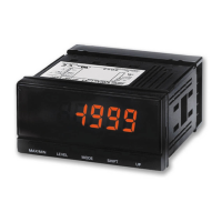
Flowrate sensorDisplaying/outputting
liquid level
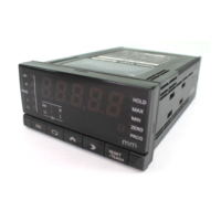
Monitoring interior
tank pressure
E8AA Pressure Sensor
4 to 20 mA
K3MA-J
Tank
Discharge valve
Pump
E4PA Ultra-
sonic Dis-
placement
Sensor
4 to 20 mA
or 0 to 10 V
K3MA-J
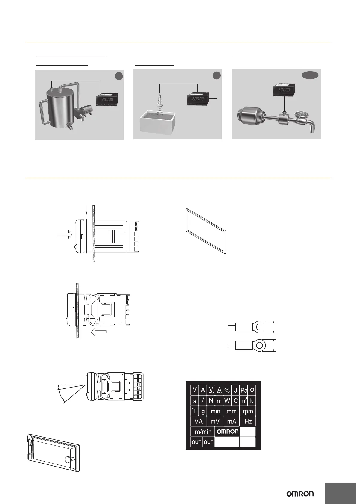
Pump
K3MA-J
4 to 20 mA
Flowrate Sensor
m/min
mm
Pa
• Monitoring gas pressure
• Inspection instruments in food or phar-
maceutical plants
• Monitoring liquid level in cleaning tanks • Monitoring send-out flowrate
• Water processing devices, etc.• Water tanks, devices using chemicals,
etc.
10°
30°
5.8 mm max.
5.8 mm max.
 Loading...