http://www.ia.omron.com/
10
(c)Copyright OMRON Corporation 2007 All Rights Reserved.
K6EL
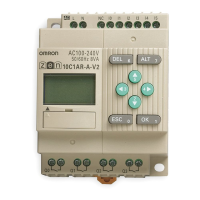
Test Circuit
Select the resistance R shown in the test circuit diagram according to
the K6EL’s rated sensed current. Change the current using the slidac
and ascertain the K6EL’s operating value each time by reading the
ammeter.
For example, R could take the values shown below:
30 mA: 3.3 k:, 6 W
100 mA: 1 k:, 20 W
200 mA: 500 :, 50 W
500 mA: 200 :, 100 W
1,000 mA: 100 :, 200 W
Safety Precautions
■ Correct Use
Installation and Wiring
• Do not, under any circumstances, connect the ZCT’s output termi-
nals k and l to ground. Doing so may result in damage to the
Relay’s internal circuits.
• Pass the primary conductor through the ZCT once.
• The Relay detects ground faults in internal wiring of devices due to
insulation deterioration and so install the ZCT as close to the power
supply side as possible.
ZCT Installation
• Install the ZCT at an outdoor cable inlet or on a ground bus bar at a
location allowing easy inspection.
• When installing on the electrical path, use a ZCT with a value
greater than the electrical path’s rated current.
• If the secondary lines run in parallel to a circuit carrying a large cur-
rent, either separate the lines as far as possible or use a shield line.
• When installing a separate-type ZCT with current flowing along the
primary conductors, short the secondary terminals using clips or
some other method.
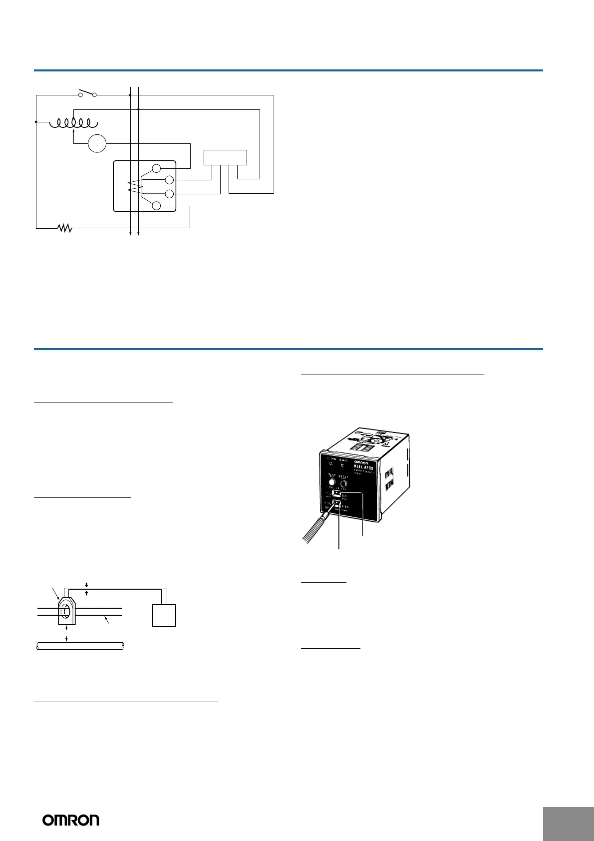
Switching the Sensed Current
1. With the K6EL-@100, 200, 500, R50, and R500, the sensed cur-
rent can be switched using a flat-bladed screwdriver.
2. The sensed current for the K6EL-30 is fixed and hence cannot be
switched.
Switching the Operating Time
1. With the K6EL-A100, A200, and A500, the operating time can be
switched using a flat-bladed screwdriver.
2. The operating time for the K6EL-30, 100, 200, 500, R50, and
R500 is fixed and hence cannot be switched.
Testing
• If the ground fault indicator (red) lights when the Relay’s test button
is pressed, it means that the internal circuits are operating nor-
mally.
• To make an overall test, run a simulated ground fault current.
Resetting
• Once manual-reset models operate, they continue to operate until
they are reset. Reset them either by pressing the reset button
(black) or by turning the control power supply OFF and ON again.
• Automatic-reset models reset automatically when the ground fault
is cleared (i.e., the current drops below the sensed current).
100 VAC
lt
l
k
kt
OTC
Switch
Slidac
mA
K6EL
Ammeter
R
ZCT
Run the secondary lines
close to each other.
K6EL
Separate by 20 cm min.
Primary conductor
Circuit carrying large curren
Sensed current selection switch
Operating time selection switch
 Loading...