http://www.ia.omron.com/
4
(c)Copyright OMRON Corporation 2007 All Rights Reserved.
K6EL
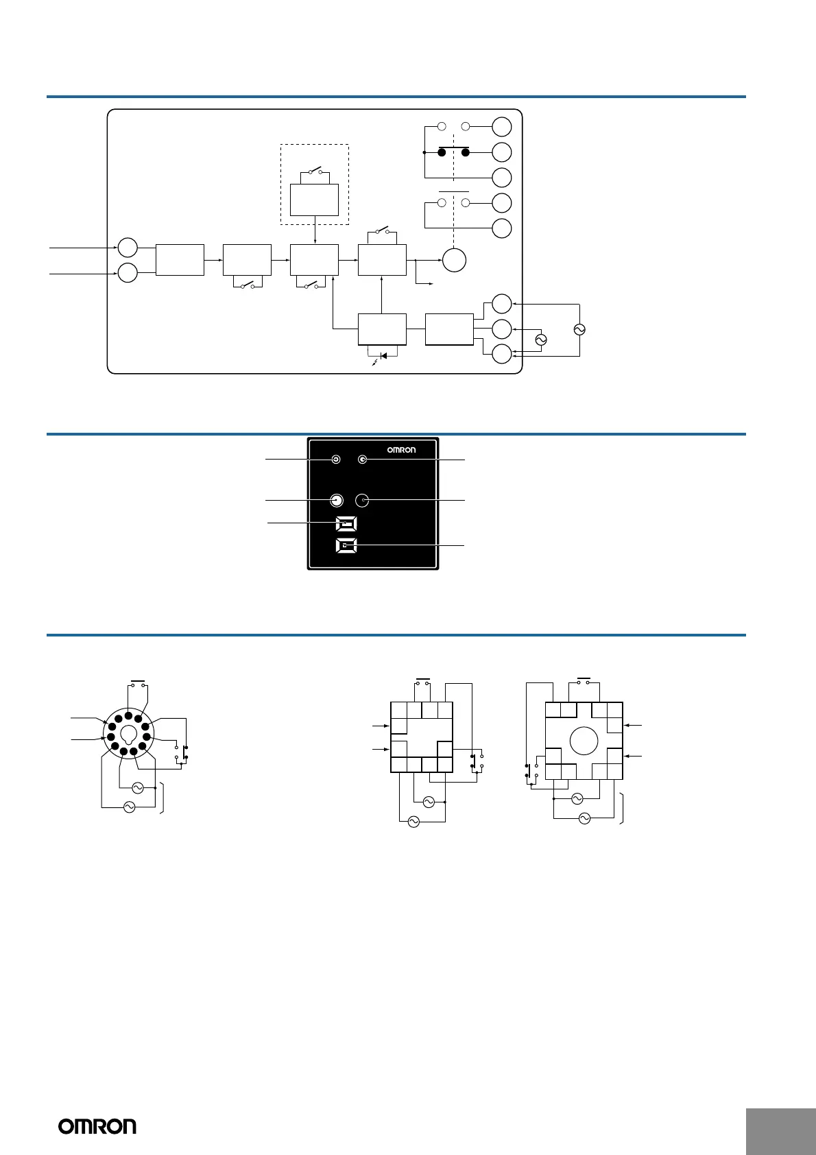
Internal Block Diagram
Nomenclature
Connections
Note: 1. The K6EL-R50 does not have terminals 6 and 7.
2. The K6EL-R500 and K6EL-R50 do not have terminal 2. (They cannot be used at 200/220 V.)
Input
protection
circuit
Operating
value setting
circuit
Shock-wave
absorption
circuit
Amplifier
circuit
Operating time
setting circuit
Switching
circuit
Test button
Power
supply
circuit
Power supply indicator (green)
Ground fault
indicator (red)
X/a
Sensitivity
selection switch
(not provided on
the K6EL-30)
From OTG ZCT
3
9
8
11
6
7
2
1
10
4
X
X/c
Reset button
Operating time
selection switch
Delayed models only
Operation at
100/110 V
(See note 1.)
(See note 2.)
Operation at
200/220 V
Note: 1. The K6EL-R50 does not
have terminals 6 and 7.
2. The K6EL-R500 and K6EL-
R50 do not have terminal 2.
(They cannot be used at 200/
220 V.)
POWER
SENSITIVITY
LEAKED
200
mA
100
mA
RESET
K6EL-A100
TEST
0.3S 0.8S
OPERATING TIME
EARTH LEAKAGE
RELAY
Ground fault indicator (red)Power supply indicator (green)
Test button (red)
Sensitivity selection switch
(not provided on the K6EL-30)
Reset button (black)
(not provided on automatic-reset models)
Operating time selection switch
(delayed models only)
6
5
4
3
2
1
11
10
9
8
7
100 VAC
200 VAC
Control power
supply
From ZCT
(See note 1.)
(See note 2.)
100 VAC
200 VAC
From ZCT
From ZCT
5678
2 1 11 10
3
4
9
100 VAC
200 VAC
Control power supply
From ZCT
From ZCT
1110 1 2
7865
93
4
Ground Fault Relay
(from Pin Side)
Ground Fault Relay with P3GA-11
(from Terminal Side)
Ground Fault Relay with P2CF-11
(from Terminal Side)
 Loading...