4 Part Names and Functions
4 - 2
NX-series EtherNet/IP Coupler Unit User’s Manual (W536)
4-1 Parts and Names
This section gives the names of the parts of the EtherNet/IP Coupler Unit, NX Units, and End Plates
and describes the functions of the parts.
This section gives the names of the parts of the EtherNet/IP Coupler Unit.
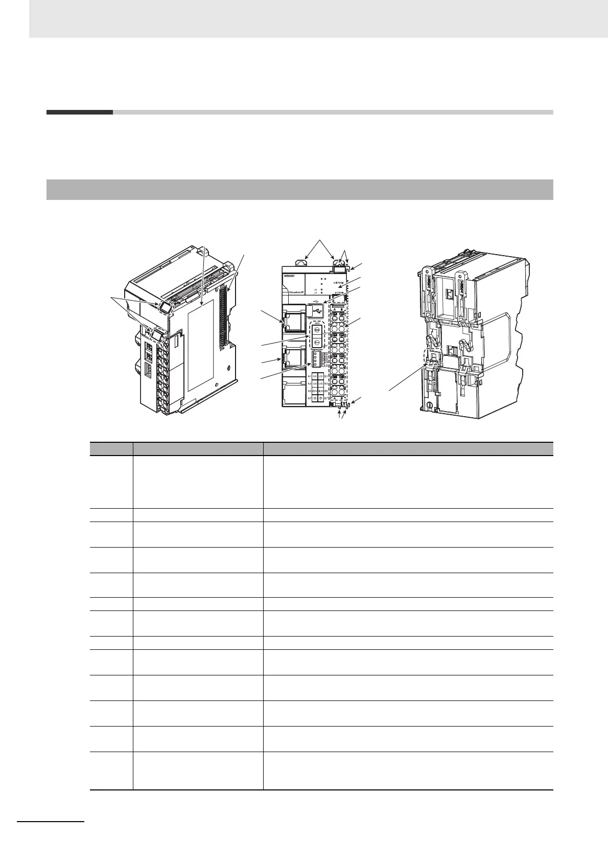
4-1-1 EtherNet/IP Coupler Units
Letter Name Function
(A) Marker attachment locations The locations where markers are attached. The markers made by
OMRON are installed for the factory setting. Commercially available
markers can also be installed.
For details, refer to 6-1-8 Attaching Markers on page 6-18.
(B) Unit specifications The specifications of the Unit are engraved in the side of the casing.
(C) NX bus connector This connector is used to connect the EtherNet/IP Coupler Unit to the
NX Unit on the right of the Coupler Unit.
(D) DIN Track mounting hooks These hooks are used to mount the EtherNet/IP Coupler Unit to a DIN
Track.
(E) Protrusions for removing the
Unit
The protrusions to hold when removing the Unit.
(F) Unit hookup guides These guides are used to connect two Units.
(G) Indicators The indicators show the current operating status of the Unit and the
status of the power supply.
(H) Peripheral USB port This port is used to connect to the Support Software.
(I) Terminal block The terminal block is used to connect to the power supply cables and
ground wire.
(J) DIN Track contact plate This plate is connected internally to the functional ground terminal on
the terminal block.
(K) DIP switch The DIP switch is used to set the default node address of the Ether-
Net/IP Coupler Unit as an EtherNet/IP slave.
(L) Communications connectors These connectors are connected to the communications cables of the
EtherNet/IP network.
(M) Rotary switches The rotary switches are used to set the last octet of the IP address of
the EtherNet/IP Coupler Unit as an EtherNet/IP Slave. The address is
set in hexadecimal.
(G)
(H)
(I)
(F)
(L)
(M)
(L)
(K)
(D)
(F)
(E)
(E)
(B)
(C)
(A)
0
1
2
3
4
5
6
7
8
9
A
B
C
D
E
F
NX-EIC202
Port1
Port2
0
1
2
3
4
5
6
7
8
9
A
B
C
D
E
F
P1
P2
MS
TS
NS
(J)

 Loading...


