3.9 Braking Resistor Installation
100 SIEPYEUOQ2A01A AC Drive Q2A Technical Manual
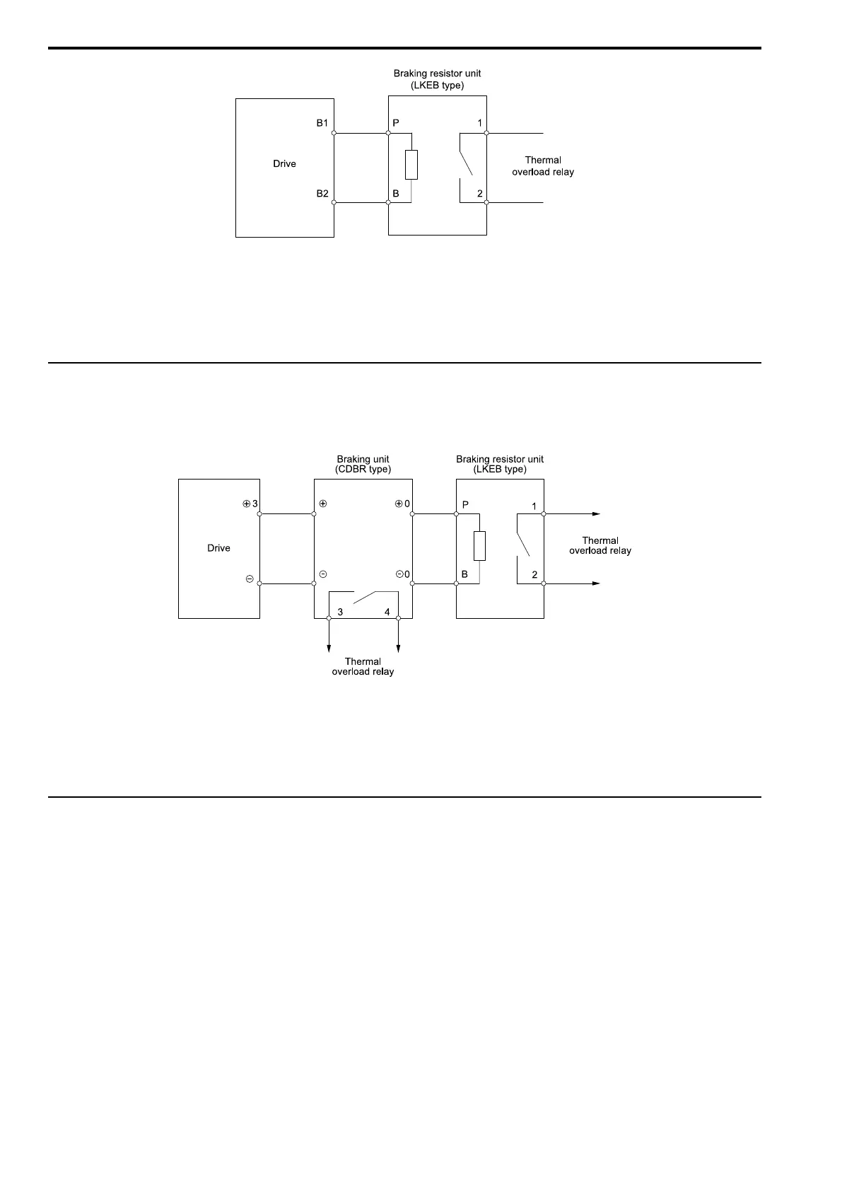
Figure 3.52 Install a Braking Resistor Unit: LKEB-Type
To install a braking resistor unit, set L8-01 = 0 [3%ERF DBR Protection = Disabled].
Models 4002 to 4168 have a built-in braking transistor.
To prevent overheating the braking resistor unit, set a sequence to de-energize the drive at the trip contacts of the
thermal overload relay.
◆ Install a Braking Unit Connection: CDBR-Type
To install a CDBR type braking unit, connect terminal +3 on the drive to terminal + on the braking unit. Then
connect terminal - on the drive to terminal - on the braking unit. Terminal +2 on the drive is not necessary for
CDBR-type braking unit connections.
Figure 3.53 Install a Braking Unit: CDBR-Type/Braking Resistor Unit: LKEB-Type
Set L8-55 = 0 [DB IGBT Protection = Disable].
Note:
To install a CDBR-type braking unit to the drive models 4002 to 4168 that have a built-in braking transistor, connect drive terminal B1
to terminal + on the braking unit.
◆ Connect Braking Units in Parallel
To connect two or more braking units in parallel, wire and select connections as shown.
 Loading...


