3-17
CHAPTER 3 Installation
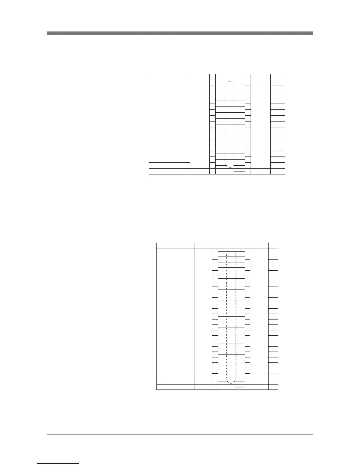
3) Signal wiring connections in the machine harness
1. R6YXCH250, R6YXCH350, R6YXCH400
Connector pins 1 to 14 can be used. Pin 15 is connected to a shield wire
and cannot be used as a signal wire.
Connector
I O
(Arm side)
NO
1
2
3
4
5
6
7
8
9
10
11
12
13
14
15
Connection NO
1
2
3
4
5
6
7
8
9
10
11
12
13
14
15
1
Connector
I O
(Base side)
FG
Color
Brown
Red
Orange
Blue
Violet
Grey
White
Black
Brown
Red
Orange
Blue
Violet
Grey
Green
Green
Signal
User signal line
Shield
Flame ground
(Robots models with non-standard specications
may have different wiring colors.)
2. R6YXC500, R6YXC600, R6YXC700, R6YXC800, R6YXC1000
Connector pins 1 to 24 can be used. Pin 25 is connected to a shield wire
and cannot be used as a signal wire.
NO
1
2
3
4
5
6
7
8
9
10
11
12
13
14
15
16
17
18
19
20
21
22
23
24
25
Signal
User signal line
Shield
Flame Ground
NO
1
2
3
4
5
6
7
8
9
10
11
12
13
14
15
16
17
18
19
20
21
22
23
24
25
1
Connector
I O
(Arm side)
Connection
Connector
I O
(Base side)
FG
Color
Brown
Red
Orange
Blue
Violet
Grey
White
Black
Brown
Red
Orange
Blue
Violet
Grey
White
Black
Brown
Red
Orange
Blue
Green
Green
(Robots models with non-standard specications
may have different wiring colors.)
 Loading...


