3-3
CHAPTER 3 Installation
1-2 Installation base
1) Prepare a sufciently rigid and stable installation base, taking account of
the robot weight including the end effector (gripper), workpiece and reac-
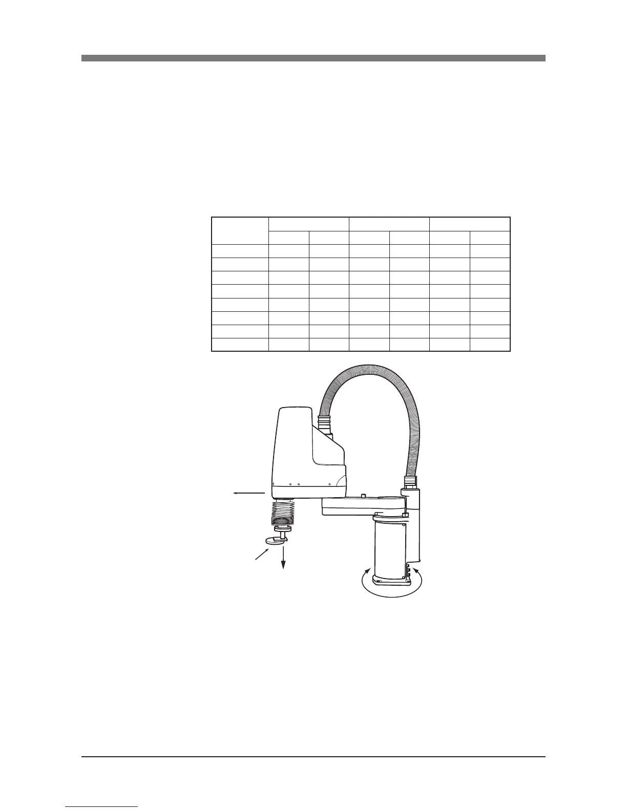
tion force while the robot is operating. The maximum reaction force (see
Fig. 3-1) applied to the X-axis and Z-axis of each robot during operation is
shown in the table below. These values are an instantaneous force applied
to the robot during operation and do not indicate the maximum load capa-
city.
The maximum reaction force
Fig. 3.1 Maximum reaction force applied during operation
2) The parallelism of the installation base surface must be machined within
a precision of ±0.05mm/500mm. The robot base mount must be installed
facing down and in a level position (except ceiling-mount models which
should be installed with the base mount facing up).
3) Tap holes into the surface of the installation base. For machining dimen-
sions and positions, refer to the dimensional outlines listed in our robot
catalog.
 Loading...


