47
The total power consumption for each Rack can be obtained from the following
formulas:
• CPU Rack: Total power consumption for each Unit + 7 (8)
0.6 x 0.55 (1)
• Expansion I/O Power Supply/Remote I/O Slave Unit:
0.6 x 0.55 (1)
Total power consumption for each Unit + 2
(VA)
(VA)
Where:
7 = Power consumption of the CPU Unit,
(8) = Power consumption of the CPU21-E/23-E,
0.6 = 60% efficiency, and
0.55 (1) = Power rate (Number in parentheses: when CPU31-E is used.)
Where:
2 = Power consumption of the I/O Power Supply or
Remote I/O Slave Unit,
0.6 = 60% efficiency, and
0.55 (1) = Power rate (Number in parentheses: when
PS211, RT002-P or RT202 is used.)
4-4 I/O Connections
Connect the I/O Devices to the I/O Units using AWG 22 (cross-sectional area of
0.3 mm
2
) for 19-terminal terminal blocks and AWG 22 to AWG 18 lead wire
(cross-sectional area of 0.3 to 0.75 mm
2
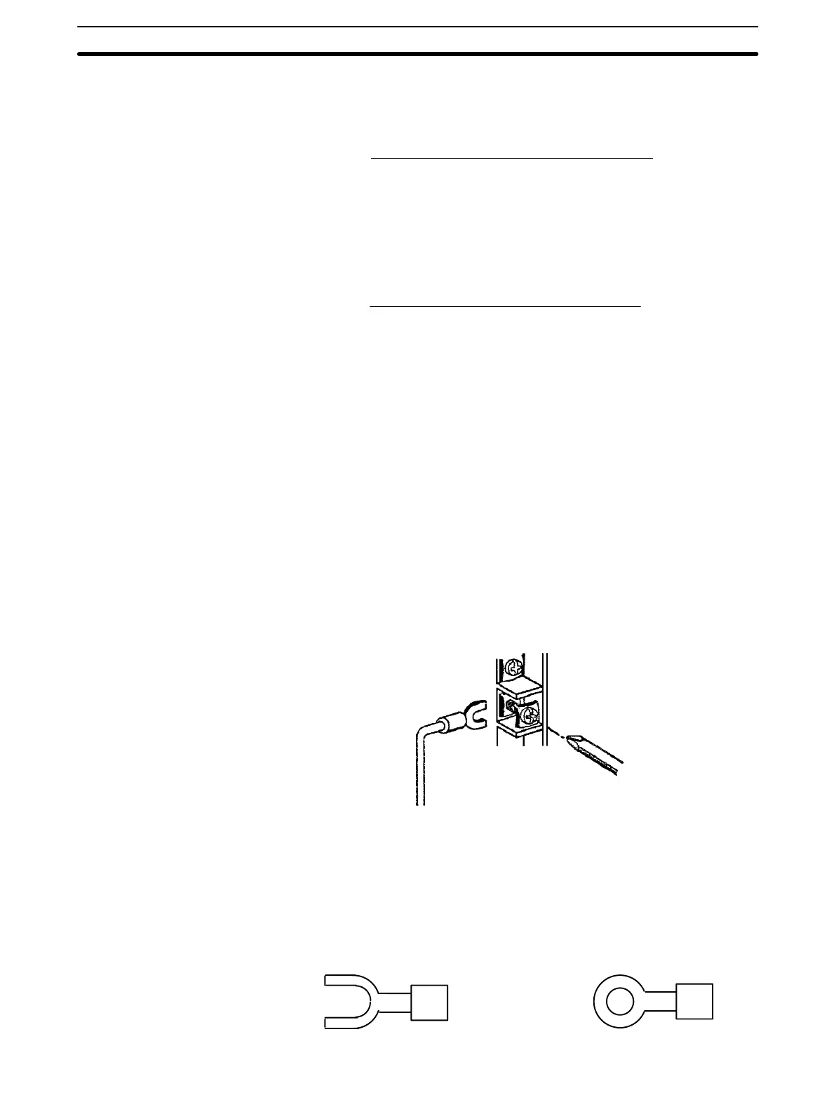
) for 10-terminal terminal blocks. The
terminals have screws with 3.5-mm diameter heads and self-raising pressure
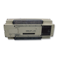
plates. Connect the lead wires to the terminals as shown below. Tighten the
screws with a torque of 0.8 N S m.
Power Supply Wiring Use 1.25-mm
2
cables or larger. The terminal blocks have screws with 3.5-mm
diameter heads and self-raising pressure plates. For connecting to the terminal
blocks, use round crimp terminals for 3.5-mm diameter heads. Directly connect-
ing stranded wires to the terminal blocks may cause a short-circuit.
Tighten the terminals on the terminal blocks to the torque of 0.8 N S m.
Calculation of Power
Consumption for Each
Rack (Examples)
I/O Connections Section 4-4
Artisan Technology Group - Quality Instrumentation ... Guaranteed | (888) 88-SOURCE | www.artisantg.com

 Loading...