Specifications Appendix B
66
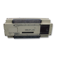
I/O Link Units
Supply voltage
Operating voltage range
Power consumption
Insulation resistance
Dielectric strength
Noise immunity
Vibration
Shock
Ambient temperature
Humidity
Grounding
Structure
Weight
Dimensions
100 to 120/200 to 240 VAC 50/60 Hz
85 to 132/ 170 to 264 VAC
15 VA max.
10 M
Ω min. (at 500 VDC) between AC terminals and housing
2,000 VAC 50/60 Hz for 1 minute (between AC terminals and housing)
1,000 V p–p, pulse width: 100 ns to 1
µs, rise time: 1 ns
10 to 35 Hz, 2 mm double amplitude, in X, Y, and Z directions, 2 hours each
10 G in X, Y, and Z directions, 3 times each
Operating: 0
° to 55°C
Storage: –20
° to 65°C
35% to 85% RH (without condensation)
Less than 100
Ω
IEC IP–30 (mounted in a panel)
1 kg max.
120(w) x 250(h) x 43(d)
Relay Service Life (at
Maximum Switching
Capacity)
Electical
Mechanical
300,000 operations [under resistive load (p.f. 1)]
100,000 operations [under inductive load (p.f. 0.4)]
50,000,000 operations
Transistor and Triac
Specifications
Max. switching capacity
Min. switching capacity
Leakage current
Residual voltage
ON–delay time
OFF–delay time
Transistor G3SD–Z01P–PD–US
1 A at 5 to 24 VDC
10 mA at 5 VDC
100
µA at 24 VDC
1.5 V max.
1.5 ms max.
1.5 ms max.
Triac G3S–201PL–PD–US
1 A at 85 to 250 VAC
10 mA at 100 VAC
20 mA at 200 VAC
2 mA at 100 VAC
5 mA at 200 VAC
1.5 V max.
1.5 ms max.
1/2 of load frequency + 1 ms max.
Do not mix output devices within the same common circuit.