27
2-6 I/O Wiring
This section shows I/O wiring diagrams for representative models of all the
CPUs, Expansion I/O Units, and I/O Link Units covered in this manual. It also
gives connection examples for the sensors and switches which can be con-
nected as input devices.
2-6-1 Unit Wiring Diagrams
The following items are all available for use as outputs. Do not mix them
within the same common circuit.
Output
Relay
Transistor
Triac
Load Power Supply
Up to 250 VAC/24 VDC
5 to 24 VDC
100 to 120/200 to 240 VAC
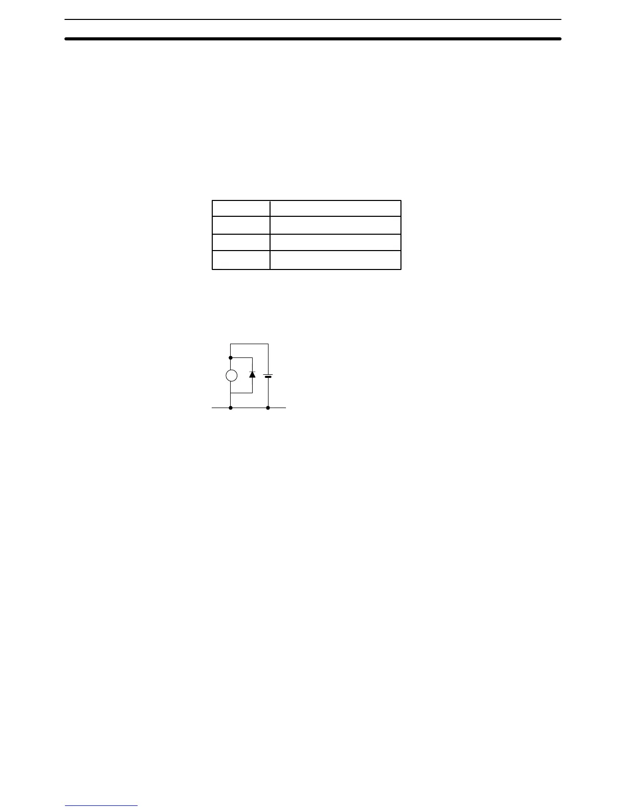
When using transistor outputs, connect the common line (COM) to the load
power supply negative side. For an induction load, connect the diode to the
load in parallel, as shown in the diagram, such that the cathode is on the
positive side of the power supply.
L
OUT COM
+
When using the high-speed counter (HDM(98)) instruction, wire input 0000
as the high-speed counter input and input 0001 as the hardware reset input.
If the HDM(98) is not used, inputs 0000 and 0001 may be used as general
input terminals. Their response time (0.15 ms), however, will be shorter than
the other inputs.
Do not connect the NC terminals to anything. The DC inputs in the following
I/O wiring diagrams are NPN (positive common). Reverse the polarity if PNP
(negative common) is used.
In the diagrams, representative models are sometimes used to cover several
models with similar wiring. In such cases, the type of Unit (i.e., CPU C60P) is
listed first, followed by the suffix of the applicable model number. A space left
blank (j) in the model number indicates that any of several numbers could
be inserted there.
I/O Wiring Section 2-6
 Loading...