45
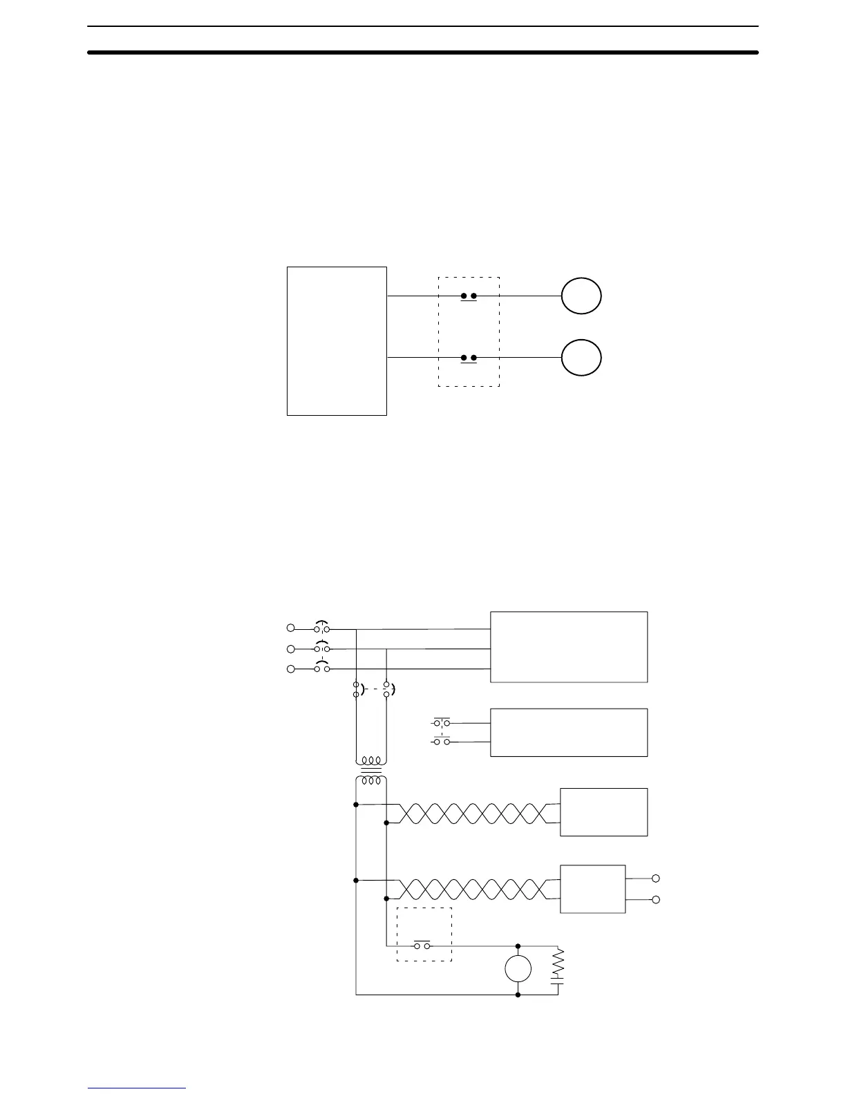
Interlock Circuit There are sometimes cases in which a PC can direct a machine to do either
of two contrasting actions, and in which damage could result from a malfunc-
tion in the PC. For example, the PC could be set up to output commands to a
motor to operate alternately in forward and reverse. In such cases an inter-
lock circuit can be set up to prevent damage in case of a malfunction. In the
example diagram below, the interlock circuit will prevent MC1 and MC2 from
turning ON at the same time even if the PC malfunctions and turns outputs
0501 and 0502 ON simultaneously.
MC1
MC2
Motor forward
Motor reverse
Interlock circuit
PC
0501
0502
Electric power systems, control systems, PC power supply systems, and I/O
power supply systems should all be wired separately, as shown in the follow-
ing diagram.
CR1
DC power
supply
PC
Control system
Electric power system
PC RUN
output
Twisted pair cable
CR!
+
–
Surge suppressor
MCB2
MCB1
Wiring of Power Supply
Systems
Special Wiring Precautions Section 2-7
 Loading...